Search the documentation
Enter at least 2 characters
Enter at least 2 characters
 |
CAE Fidesys 9.0 Documentation |
This section presents the main functions of the Fidesys graphical user interface using the example of creating a geometric model in the form of a parallelepiped with a through hole and constructing a finite element mesh on this model (see Fig. 1).
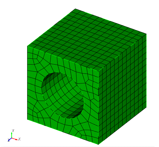
Fig. 1 - Generated mesh for a parallelepiped (cube) with a cylindrical hole
If your version of Fidesys does not have a GUI, then follow the steps specified in the second column of the CL table (or go to the Manual section Example of using the command line), if there is a GUI, then follow the steps of the first column:
Table 1 Basic steps
| GUI | CL | |
| Step 1 | Step 1 | Start execution |
| Step 2 | Step 2 | Creating a brick |
| Step 3 | Step 3 | Creating a cylinder |
| Step 4 | Step 4 | Setting up graphical display |
| Step 5 | Step 5 | Hole Formation |
| Step 6 | Step 6 | Setting the sizes of mesh elements |
| Step 7 | Step 7 | Surface mesh generation |
| Step 8 | Step 8 | Volumetric mesh generation |
| Step 9 | Step 9 | Mesh quality check |
| Step 10 | Step 10 | Definition of element type and assignment of boundary conditions |
| Step 11 | Step 11 | Mesh export |
Some explanations for the example provided:
Each instruction has a step number. Following these steps, you will perform a series of actions corresponding to solving the problem.
The screenshots and other images provided show what you should see on the screen as you follow the instructions.
All command line options have the following general form:

