Search the documentation
Enter at least 2 characters
Enter at least 2 characters
 |
CAE Fidesys 9.0 Documentation |
This instruction demonstrates the use of the Fidesys command line using the example of creating a geometric model in the form of a brick with a through hole and constructing a finite element mesh on this model. The main steps for completing this task are:
Each of these steps is described in detail in the following subsections. The geometric entity under consideration (a brick with a cylindrical hole passing through its center) is shown in Fig. 1. The identification numbers (IDs) of the curves and surfaces, which are referenced in the command line commands corresponding to each step, are also presented there. The resulting mesh model is shown in Fig. 2.
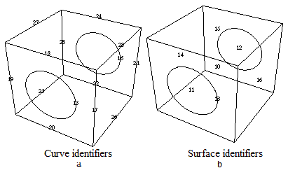
Fig. 1 Geometric model of a brick (cube)
with a cylindrical hole:
a - curve IDs are shown; b - surface IDs are shown
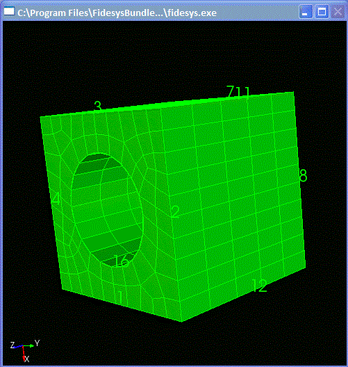
Fig. 2 Generated mesh for a brick (cube) with a cylindrical hole

