Search the documentation
Enter at least 2 characters
Enter at least 2 characters
 |
CAE Fidesys 9.0 Documentation |
The volumetric geometric model created in step 5 will be broken down into elements according to the Sweep scheme, according to which the surface mesh created on one side of the brick (the so-called initial surface) is "sweeped" from this side to the opposite (final surface). Before generating any mesh, the user must specify the size of the generated elements (the division interval). In the example under consideration, one element size will be set for the main part of the volume and a smaller size for the area around the hole. The number of intervals will be set directly in the direction of the pull.
To set the interval for the main part of the volume, enter the command:
FIDESYS> volume 1 size 1.0
Since the brick has a length of 10 along each side, this command specifies that each straight line is divided into 10 elements.
For the purpose of better partitioning in the hole area, we set a smaller interval size for the curve in the xy plane that forms the hole outline. To determine the ID of this curve, you must either select it with the mouse (see the Selecting objects with the mouse section), or enable the labels of entity curves mode and update the image. To display labels and update the image, use the commands:
FIDESYS> label curve on
FIDESYS> display
The default size of the captions can sometimes be too small to read. To change the size of the text characters, you can use the commands:
FIDESYS> graphics text size 2
FIDESYS> display
The result is shown in Fig. 8. After performing the specified actions, you can set the size of the elements for the displayed curve:
FIDESYS> curve 16 size 0.5
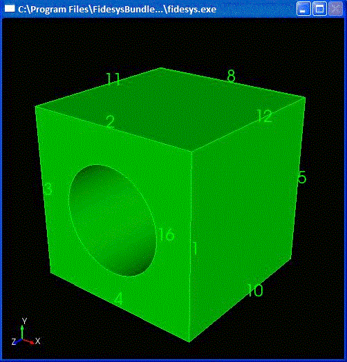
Fig. 8 Geometry with curve label mode enabled
Finally, we would like to generate exactly 5 layers of elements in the pull direction. This is done by specifying the number of intervals on the line 11 (the term "curve" is used for any type of line):
FIDESYS> curve 11 interval 5

