Search the documentation
Enter at least 2 characters
Enter at least 2 characters
 |
CAE Fidesys 9.0 Documentation |
We can begin to create a geometric model on which the mesh will then be built. Create a brick with a width of 10, a depth of 10, and a height of 10, i.e. a cube. The width and depth correspond to the x and y dimensions (coordinate axes) of the entity being created; they are measured horizontally and vertically on the screen. The height, or z dimension, extends out of the plane of the screen.
On the Command Bar, select Mode - Geometry, then Entity - Volume, then Action - Create. In the drop-down list, Brick appears by default (Fig. 3):
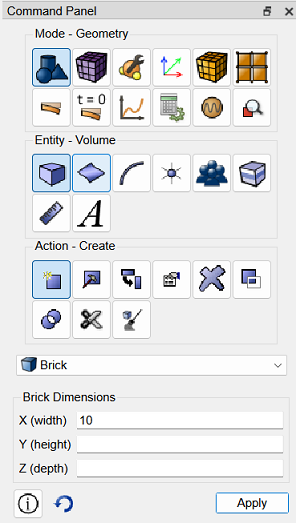
Fig. 3 - Command bar view
Enter the X, Y, Z values. Note that the X (width) value is 10 by default. Click Apply to create the geometric model.
The created brick (cube) will appear in the graphics window, as shown in Fig.4:
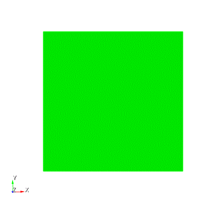
Fig. 4 - Result of step 2
If you want to change the appearance of your model, click on one of the icons on the Toolbar that are responsible for the visualization mode:
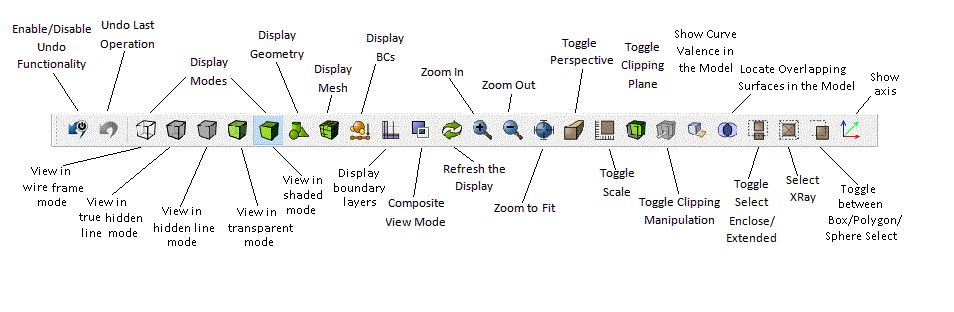
Fig. 5 - Functions of the icons on the Toolbar

