Search the documentation
Enter at least 2 characters
Enter at least 2 characters
 |
CAE Fidesys 9.0 Documentation |
As boundary conditions are considered: imposed to the object (analyzed structure) of the connection, or constraints applied to the object loads and conditions contact objects. Also for boundary conditions it is possible task depending on time or coordinates. Information about creating and changing boundary conditions can be found at the appropriate links. Additional the information is contained in the subsections:
Boundary conditions can be set for a set of nodes or a set of sides. These sets can be formed from geometric or grid objects. If geometric sets of nodes or sides are used, then when rebuilding grid data about the imposed boundary conditions are not lost.
The sets of nodes or sides used to set boundary conditions are visible to the user and they can be changed separately from the boundary conditions. Sets nodes or sides can be used to set boundary conditions or removed of them at any time.
When creating boundary conditions, constraints are included in the set of constraints, loads are included in the set of loads, and contact conditions are included in the set of contacts. A set of boundary conditions can consist of an arbitrary number of constraints, loads and contact pairs.
CAE Fidesys supports the following types of boundary conditions:
- Restrints:
- Loads:
fluid flow;
fluid source;
volumetric fluid source.
To set boundary conditions:
1. On the command bar, select the Mode - Boundary Conditions.
2. Select the type of boundary condition in the Entity - Block.
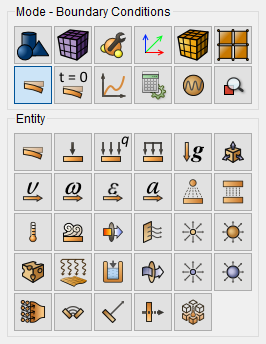
3. Select Action - Create. Set the following parameters:
ID/Name (assign a new ID, enter a name using letters and/or digits or leave an automatically assigned ID number);
the object to which the boundary condition is applied (volume, surface, curve, edge, vertex, node, set of nodes, element, face, set of sides);
Object ID (put the pointer in the Object ID field and select click on the required objects, their numbers will be entered in this field automatically. If you need to specify several objects, select them by holding Ctrl key);
other parameters (value, degrees of freedom, etc.).
4. Click Apply.
Using the functionality available through the command bar, you can also view list of specified boundary conditions, change and delete the previously specified boundary condition.