Search the documentation
Enter at least 2 characters
Enter at least 2 characters
 |
CAE Fidesys 9.0 Documentation |
The user can set the direction relationship for symmetry modeling. To do this, follow these steps:
On the Command Bar, select Mode - Boundary Conditions.
Select Entity - Direction Restraint
Depending on the situation, choose Action - Create or Action - Modify .
Using graphical user interface elements set the identifier (ID) of the entity for which the boundary value is applied condition, specify the type (Movement, Speed, Acceleration) and direction (Normal or Vector).
Click Apply.
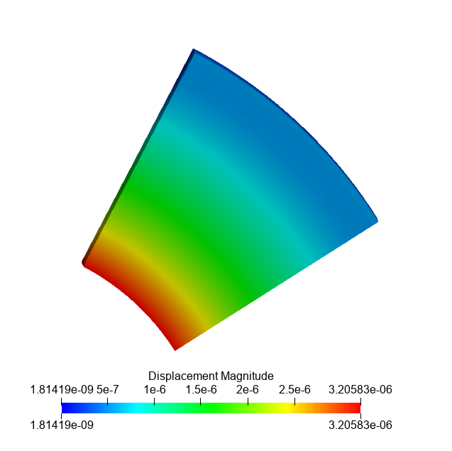
The Lame problem, a pressure of 1 MPa is applied to the outer face. Considered a sector of 30o.
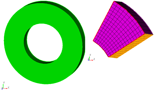
Comparison of displacements for a sector b in 30o of the original model
Example of a working script for setting communication in the direction:
reset
create Cylinder height 0.5 radius 2
create Cylinder height 0.5 radius 1
subtract volume 2 from volume 1
webcut volume 1with plane yplane offset 0 rotate 30 about z center 0 0 0
webcut volume 3 with plane yplane offset 0 rotate 60 about z center 0 0 0
delete Volume 1
delete Volume 4
volume allsize auto factor 5
mesh volume all
create pressure on surface 26 magnitude 1e6
create pressure on surface 24 magnitude 0.5e6
create material 1
modify material 1 set property 'POISSON' value 0.3
modify material 1 set property 'MODULUS' value 200e9
set duplicate block elements off
block 1 volume all
block 1 material 'Material 1'
block 1 element solid order 2
create directionrestraint on surface 17 displacement value 0 normal
create directionrestraint on surface 22 displacement value 0 normal
create directionrestraint on surface 23 displacement value 0 normal
analysis type static elasticity dim3