Search the documentation
Enter at least 2 characters
Enter at least 2 characters
 |
CAE Fidesys 9.0 Documentation |
A "thermal gap" type contact is used to solve thermal conductivity problems or related thermoelastic problems in structures with small gaps filled with various compressible or displayable media that cannot be modeled directly using finite elements due to their potentially small size and/or possible significant deformation of the elements in the process of solving the problem due to the overlap of the gap when installed in in this area of mechanical contact.
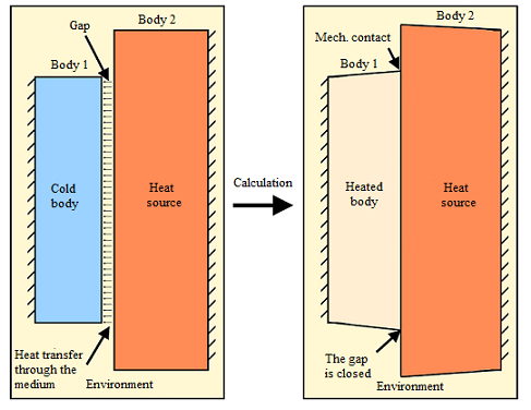
Fig. 1 – Task schema
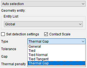
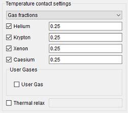
The first way is through the gas mixture; the second way is through the material ID, in which the heat transfer coefficient is to be specified.
The calculations use the Chapman-Enskog theory and the Lennard–Johnson potential, the parameters of which are set (molar mass [g/mol], the diameter of the interaction cross section [A] and the interaction energy [K]). The interface has preset gases (Helium, Krypton, Xenon, Caesium). The mixture is given in terms of the moles of fractions, the sum of which should be equal to 1.
An important pair of solver settings is the stiffness of the thermal contact and the coefficient of lower relaxation. The first coefficient specifies the accuracy with which the thermal clearance is performed. With an increase in the stiffness requirement, instability of the solution may appear – for stabilization, it is necessary to use the lower relaxation coefficient (0; 1]. The lower the coefficient, the more stable the calculation scheme, but the slower the convergence.
There is no need to neglect the initial conditions of the problem: due to the radiant heat transfer in the gap, the problem is nonlinear. A decrease in the relaxation coefficient can be avoided by setting more precise initial conditions.
Unlike mechanical contact, heat transfer is carried out through the medium over considerable distances. The "gap" parameter is responsible for the distance between entities at which the thermal gap model is activated.
To account for radiant heat transfer, it is necessary to set the emissivity in materials that correspond to the main and secondary entities of the contact. The model uses the approximation of a small distance between entities (when radiant heat transfer along the gap can be neglected).
The calculation takes into account the compression/expansion of the heat flux density during the transition from the secondary entity of the contact to the main one. I.e., it is taken into account that the area of the secondary entity differs from the area of the main entity. The contact area inside the thermal gap is interpolated linearly (this corresponds to a cylindrical wall).
The thermal gap supports two-dimensional settings, including axial symmetry. In this case, the curvilinearity of the contact is determined by the radial coordinate of the contact entities.
The temperature distribution in the thermal gap is considered quasi-stationary (i.e., the heat capacity of the medium in the thermal gap is zero).
In most cases, the coefficient of thermal conductivity depends on temperature, to account for this dependence, you need to set the lower, upper bound and temperature step. When going beyond the range, the thermal conductivity coefficient is considered constant.
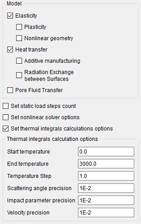
This paragraph applies only to the first method of setting the gas gap (through a mixture of gases). Before performing the basic calculations, collision integrals in Chapman-Enskog theory are calculated. To calculate, you need to set accuracy parameters (by aiming parameter, by scattering angle, by speed). By default, they are set to 1E-2. When setting a higher calculation accuracy, it may take a significant amount of time – in order not to waste it, data is saved in the "CollisionMomentsData.bin" file in the calculation folder during repeated runs. If the calculation accuracy parameters match, the data will be read (only in console mode).
The result fields that relate to the contact area contain "thermal conductivity" in the name.
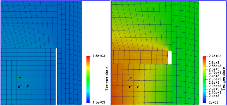
Fig. 2 – Gap bridging in the structure during deformation