Search the documentation
Enter at least 2 characters
Enter at least 2 characters
 |
CAE Fidesys 9.0 Documentation |
Contact problems are highly nonlinear and require significant computer resources to be solved. Thus, to select the model resulting in the most effective solution, it is very important to understand the physical content of the problem. Two factors determine nonlinear nature of contact problems. Firstly, the contact area and therefore the boundary conditions are unknown until you get the solution. Secondly, it is necessary to take friction into account in many contact problems. Effects related to the friction can result in poorly converging problems.
The contact's actions include:
To create a contact on the command bar, select the (Mode — Boundary Conditions, Entity — Contact, Action — Create).
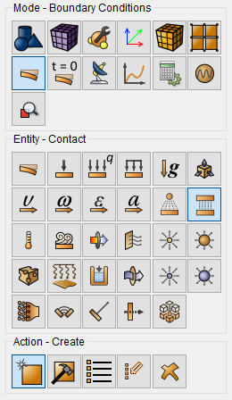
In CAE Fidesys, the creation of contact interactions is implemented automatically or manually.
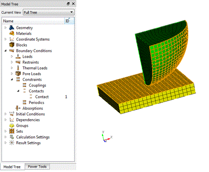
Each contact pair is assigned an individual number (ID) and a set of properties. The number of contact pairs is unlimited. To visualize the created contact pair, click on the name of the required contact pair in the same entity tree on the left. The selected pair will be highlighted in yellow on the model.
The automatic creation of contacts is implemented through Auto selection and occurs based on the type of entity that is selected in the Geometry entity - Entity List window and has a choice:
Global - for all high-order entities;
Volume - among the selected volumes within the accuracy of the search;
Surface - among the selected surfaces within the accuracy of the search;
Curve - among the selected curves within the accuracy of the search.
When a contact is automatically created, the following options are available Set detection settings and Contact Scale.
Set detection settings contain settings - Detection Tolerance and Search Value. When this setting is enabled, the contact search radius will add up with Tolerance.
Contact Scale takes into account surfaces with a small area. By default, the option is enabled for automatic search of contact pairs and disabled when manually selecting the main and secondary entities.
Manual contact creation is implemented through Master and Slave selection.
Entity List available for selecting the main and secondary entities: Surface, Curve, Vertex, Node, Tri, Face/Quad, Edge, Nodeset, Sideset.
Types of contacts:
General/General (with zero friction);
Tied/Tied Normal/Tied Tangent;
Thermal Gap;
Tied - the type of contact in which the master and the slave entity are connected ("glued") the contact area between each other and the contact area does not change under the influence of the applied load. Sliding between the faces or edges, as well as their separation (violation of contact) is not allowed.
Tied by normal - a type of contact similar to a connected one, in which the separation of master and slave entities in the normal direction is not allowed, but the slip of the contact surface is allowed.
Tied by tangent - a type of contact similar to a connected one, in which the master and slave entities are not allowed to slip tangentially, but the separation of the contact surfaces is allowed.
In the tied by target contact implemented Preload. Its value is set in units of force.
Tolerance - this is the contact search area, i.e. the maximum radius of the contact node search area during the calculation.
The following contact algorithms are implemented in CAE Fidesys:
Auto - automatic replacement depending on the type of contact: if connected, it automatically changes to the MPC method, if common, then to the penalty method with default settings.
To add changes to the command bar, select (Mode - Boundary Conditions, Entity - Contact, Action - Modify). This function allows you to change the following parameters for the selected contact IDs: Type, Tolerance, Method, as well as their settings.
To display a list of contact data or save data to a file on the command bar, select (Mode - Boundary Conditions, Entity - Contact, Action - List).
To graphically display contacts on the command bar, select (Mode - Boundary Conditions, Entity - Contact, Action - Draw).
The contact is deleted by ID as follows (Mode - Boundary Conditions, Entity - Contact, Action - Delete).
In Fidesys Viewer, after performing the calculation, you can evaluate the behavior of each contact element by the status assigned to it in the Contact Status Node:
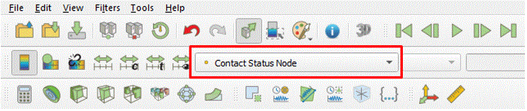
This field has one component, which has one of the following values:
0 - no contact;
1 - there is a contact, but the connection in the node is not recorded to avoid redefining the connections;
2 - there is a contact, the tied is normal;
3 - there is a contact, normal and tangent tied;
4 - there is a contact, the tied is normal and tangential slip;
5 - there is a contact, the tied tangent.
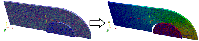
- Method MPC - multipoint constraint, a contact method using coupling equations. Integration points (Gaussian) are used instead of nodes. The MPC method imposes requirements of non-penetration and equality of normal voltages, for which the Direct elimination method is used. This approach does not require the selection of stiffness and provides a solution in one iteration (if the contact zone does not change);
- Method Penalty - a contact method in which it is required to specify contact stiffness, which refers to the stiffness of elastic elements (virtual springs) added by the program to communicate between the entities being contacted.
The stiffness value is calculated by the program independently, depending on the material properties of the deformed elements, but the user can scale it by multiplying it by the required coefficient.
General recommendations for choosing a multiplier for normal contact stiffness by the method Penalty:
for tasks with a predominance of bending and displacement of rigid bodies, a value from 0.001 to 0.1 is recommended;
for tasks with a connected contact, the normal contact stiffness coefficient can reach up to 1000, and for other contact models up to 1.
General recommendations for choosing a multiplier for tangential contact stiffness:
for tasks with a predominance of bending and tangential movements of rigid bodies, it is recommended to reduce the value;
the maximum value is 0.5, the minimum value is limited to 0, but it is not recommended to set values less than 0.01.
Thermal penalty determines the accuracy of the temperature equality in the contact area. Thermal penalty is a Nusselt number with a characteristic size equal to the size of the mesh. The higher the value of the parameter, the more precisely the temperature equality is observed.
- The Lagrange method is used for contact problems where it is important to more accurately satisfy the non-penetration condition between surfaces. Unlike the Penalty method, here contact is defined not through stiffness, but through additional contact unknowns—Lagrange multipliers. This reduces the dependence of the result on the penalty stiffness, but makes the problem more sensitive to the settings and unnecessary constraints in the model.
IMPORTANT: The Lagrange method is implemented only for static problems.
The interface combines the method into a single mode—Lagrange. It is typically configured from simple to complex: first, normal contact without a tangential part, then, if necessary, adhesion, friction, detachment, and shear constraints are enabled.
Interface fields for the Lagrange method:
Stabilization parameter. Numerical stabilization of the Lagrange multipliers. This parameter is necessary to prevent the matrix from becoming singular or ill-conditioned. Recommended initial value: 1e-20. If the calculation fails due to a singular matrix or ill-conditionedness, the parameter can be gradually increased: 1e-18, 1e-16, 1e-15. This is not a physical contact stiffness, but merely a small numerical addition for stability.
Penetration tolerance. If enabled, the contact is activated only after penetration exceeds the specified value. The unit is the same as the model geometry: if the model is in meters, the value is in meters; if in millimeters, then the value is in millimeters. A low value provides more strict contact, but may result in frequent switching on and off of contact points. A high value makes the contact switch more smoothly, but allows for greater surface penetration before activation.
Critical Tensile Stress. If enabled, the detachment limit is set. When the normal contact reaction begins to extend beyond this value, the contact opens. The units should correspond to the model's force system. In the standard SI formulation, this can be specified as stress in Pa. A lower value means the contact opens more easily. A value that is too high may hold the contact where, according to physics, detachment should already occur.
Add stick steps. Enables preliminary checking for the stick state. The method first tries to consider the contact as stuck, then checks whether it should transition to sliding. Useful for problems with friction and stick-slip transitions. For simple contacts without friction, this parameter is usually unnecessary.
Tangential Limit. Enables the tangential portion of contact. If this option is disabled, only normal contact is enabled: the surfaces do not pass through each other but can slide freely. This should be enabled if you need to account for friction, adhesion, or tangentially connect surfaces. If the calculation converges worse after enabling this option, first reduce the "Sliding Speed."
Sliding velocity. The parameter of the tangent activity during sliding. This is not the physical speed of the body in m/s, but a numerical coefficient that determines how sharply the tangent constraint operates. The initial value can be 1. If convergence is poor, decrease it: 0.1, 0.01, or sometimes lower. The higher the value, the stiffer and sharper the tangent. The lower the value, the smoother the transition to sliding.
Critical Shear Stress. If checked, the upper limit of the shear contact reaction is set. This helps to eliminate sharp friction spikes and excessively high shear forces. The units are the same as for the shear contact stress/reaction in the selected system of units. For SI units, Pa is typically used. If the field is not specified, the shear reaction limit is not actually used.