Search the documentation
Enter at least 2 characters
Enter at least 2 characters
 |
CAE Fidesys 9.0 Documentation |
Connections are equations that are used to define constraints between nodes of a finite element model. Links are used to create simplified models.
The following types of connections are implemented in CAE Fidesys:
Variables;
Temperature;
Pore Pressure;
Distance between entities;
Direction;
Interpolation.
To set rigid coupling between bodies on the Command Panel, you must select Mode - Boundary Conditions, Entity - Coupling Constraint.
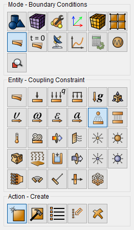
To reduce the number of errors in applying links and increase productivity, all links are brought to a common form: the maximum number of main nodes in a link is now one, restrictions on the number of nodes are not applied to side entities.

First of all, the user must decide on the way to create links. The drop-down list of ways to set links is the first in the link widget. The Fidesys PC offers two options for creating connections – automatic and direct.
The direct method (Master and Slave selection) is used to create 1 specific connection. To do this, select the type of entity to be created in the Master Entity list. The entity options for the main entity for this method are a vertex, a node, and a set of nodes containing 1 node. In the entity ID, put 1 node, vertex, or node set number. The node and vertex can be selected interactively with a mouse click. In the Slave Entity, you can select any type and number of entities, depending on the task being solved. All nodes specified in the side entity will fall into the specified coupling.
Auto selection of the nearest pairs is used to create a simple connection all the time. This method is set as the default choice. The Master Entity for this method is limited to the following list – vertex, node, set of nodes. Unlike the direct answer to this question, the main point may be that 1, and most likely, it can support a large number of users. In the Slave Entity, you can select any type and number of entities, depending on the task being solved.
With the automatic method of setting the connection, the algorithm passes sequentially through all the nodes specified in the main entity, trying to create a separate coupling for each of them.

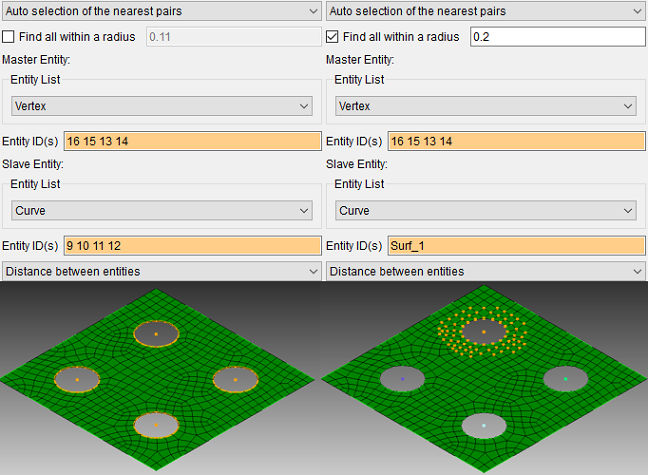
There are two auto-selection algorithms that differ in the methods of searching for side entities. Switching between algorithms takes place by enabling and disabling the "Find all within a radius" option. This option is disabled by default. With the "Find all within a radius" option disabled, the algorithm will find 1 entity closest to the main node from the list of side nodes and add it to the link. The entity will be found at any distance. When the "Find all within a radius" option is enabled, the algorithm will find in the list of side entities all those closest to the main one.
An example of how the "Auto selection of the nearest pairs" algorithm works on a cutout plate. Both algorithms have created 4 couplings. Without the "Find all within a radius" option enabled, the algorithm found the closest entity (line) to the main one and created a connection with it. With the "Find all within a radius" option enabled, the algorithm found all nodes in the set nodes falling within the radius created a connection between them and the main entity.
A detailed example can be found here
Coupling constraint variables there are two types – with a given stiffness and without.
In order to create an absolutely rigid coupling, you need to tick the boxes on those variables that you want to limit and leave the stiffness field empty. To create an elastic coupling by variables, you need to specify the stiffness value in the direction of variables. Variables can be set in both global and local coordinate systems.
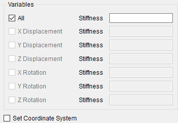
Rigid couplings by variables are used to create kinematic connections. It is recommended to create this coupling only for matching nodes. Otherwise, there may be an attached moment that will not be displayed in the reactions, It is forbidden to assign the same side entity to several main nodes. Such a statement may lead to errors or non-convergence of the solution.
A step-by-step example of creating a connection by variables
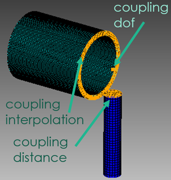
If you want to simulate a hinge coupling between three-dimensional bodies/shells, then you should create a separate "Point" type block, which will contain two vertices (with the same coordinates), which will be the center of the hinge joint. And already these points are connected by coupling by distance or interpolation, depending on the conditions of the task.
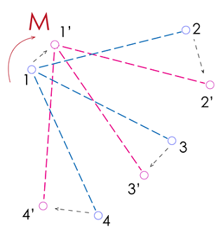
Coupling by variables equates the variables of the slave entities to the variables of the master entity. The figure shows an example where a relationship is set by variables with the master entity vertex 1 and the slave entities of vertex 2, 3, 4. If a Z-axis moment equal to Mz comes to such a coupling, then an inverse moment equal to -Mz will be formed in it. Such coupling will prevent rotation, since the movements of the master entity Ux1 are equivalent to the movements of the slave entities Ax2, Ax3, Ax4. If the rotation should slip into coupling, then it should be replaced by coupling by distance.
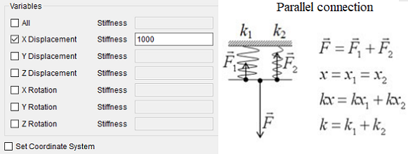
Elastic coupling by degrees of freedom are used to create springs. The number of springs in coupling will depend on the number of slave entities. The resulting couling stiffness will be equal to the number of side nodes multiplied by the specified stiffness, as for a group of parallel springs. On elastic coupling, there are no restrictions on the distance between the master and the side nodes and the recommended number of side nodes.
Coupling type Temperature and Pore pressure work similarly to coupling variables, only temperature and pore pressure serve as variables. In such a coupling, the master entity should also contain only 1 node and there should be no intersections of slave entities between the couplings.
Coupling distance between entities – works as a rigid coupling. Coupling keeps the geometric distance between the master node and the slave nodes constant. In such a coupling, the master entity should also contain only 1 node and there should be no intersections of slave entities between the couplings.
Such coupling is often used to model attachments on engineering products or to transfer moments to a three-dimensional body. In this coupling, there are no restrictions on rotation, unlike coupling by variables, and coupling nodes can rotate as a rigid whole.
Coupling repeats the functionality of coupling by variables, its feature is the automatic selection of the direction of variables (and not orientation by coordinate system). It is recommended to always set the stiffness coupling direction.
Coupling interpolation is an analog of coupling RBE3. It is used where coupling by distance is not applicable due to its rigidity. Learn more about coupling RBE3.
Step-by-step example of creating coupling by variables
The difference between couplings by variables, by distance and interpolation is described in detail here.
The following commands are used to create hard links:
create coupling [[id] <id>] [name <name>] master {volume|surface|curve|vertex|node|nodeset} {[[id] {[<id>] [<id range=" " start=" "> to <id range=" " finish=" ">]}...] [all]} slave {volume|surface|curve|vertex|node|nodeset} {[[id] {[<id>] [<id range=" " start=" "> to <id range=" " finish=" ">]}...] [all]} {dofs <x displacement=" "> <y displacement=" "> <z displacement=" "> <x rotation=" "> <y rotation=" "> < rotation=" "> [stiffness <stiffness>]|temperature|porepressure|distance} [cs {<id>|<name>}] [step {[[id] {[<id>] [<id range=" " start=" "> to <id range=" " finish=" ">]}...] [all]}]
To change the names of dependent and independent objects, use the following commands:
modify coupling {[[id] {[<id>] [<id range start> to <id range finish>]}...] [<name>] [all]} [name <name>] [master {volume|surface|curve|vertex|node|nodeset} {[[id] {[<id>] [<id range start> to <id range finish>]}...] [all]}] [slave {volume|surface|curve|vertex|node|nodeset} {[[id] {[<id>] [<id range start> to <id range finish>]}...] [all]}] [{dofs <X Displacement> <Y Displacement> <Z Displacement> <X Rotation> <Y Rotation> <Z Rotation> [stiffness <Stiffness>]|temperature|porepressure|distance}] [cs {<id>|<name>}] [step {[[id] {[<id>] [<id range start> to <id range finish>]}...] [all]}]
To remove hard coupling, the following commands are used:
delete coupling <id_range>