Search the documentation
Enter at least 2 characters
Enter at least 2 characters
 |
CAE Fidesys 9.0 Documentation |
This example serves to demonstrate a convenient way to create connections between a large number of entities. To do this, use the creation method connections using automatic selection of the nearest pairs. This example uses communication by distance, but the approach is applicable for any types of connections. With him you can use it to connect all types of entities (geometric and finite element), and also use ready-made nodesets.
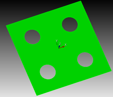
We consider an example of a static calculation of a plate that is fixed along two parallel edges. The plate has 4 round holes. In the center holes there are vertices to which forces are applied from the plane plates. The vertices are attached to the holes using the “distance between” connection. entities. For such a connection to work, you need to add vertices to a separate block of the “Point” or “Located Mass” category, so that the vertex is split into an element with 1 node.
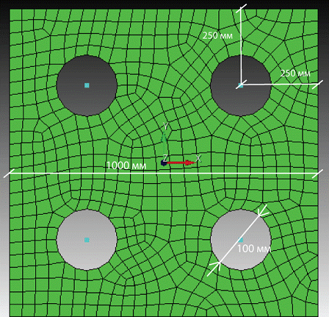
The plate is loaded with point forces of 1 MN, the forces are applied to free vertices. Material parameters: Young's modulus E = 2e11 Pa, coefficient Poisson n = 0.3, density r = 7800 kg/m3.
1. Create the line surface of the future plate.
On the command bar, select the module for constructing surface geometry (Mode - Geometry, Entity - Surface, Action - Create).

Select Rectangle in the list of geometric elements.
Set the parameters:
Width: 1
Height: 1;
Location: ZPlane.
Click Apply.
2. Create the first surface for the future hole.
On the command bar, select the module for constructing surface geometry (Mode - Geometry, Entity - Surface, Action - Create).
From the list of geometric primitives, select Circle.
Set the block dimensions:
Specify Circle Using: Radius;
Radius: 0.1;
ZPlane.
Click Apply.
3. Create a second surface for the future hole.
From the list of geometric primitives, select Circle.
Set block dimensions:
Specify Circle Using: Radius;
Radius: 0.1;
ZPlane.
Click Apply.
4. Create a third surface for the future hole.
From the list of geometric primitives, select Circle.
Set block dimensions:
Specify Circle Using: Radius;
Radius: 0.1;
ZPlane.
Click Apply.
5. Create a fourth surface for the future hole.
From the list of geometric primitives, select Circle.
Set block dimensions:
Specify Circle Using: Radius;
Radius: 0.1;
ZPlane.
Click Apply.
6. Move the first surface to the location of the future hole.
On the command bar, select the surface geometry module (Mode - Geometry, Entity - Surface, Action - Transform).
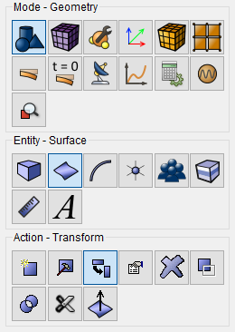
From the list of geometric primitives, select Move.
Set the required parameters:
Surface ID(s): 2;
Include Merged;
Select Method: Distance;
X Distance: 0.25;
Y Distance: 0.25.
Click Apply.
7. Move the second surface to the location of the future hole.
From the list of geometric primitives, select Move.
Set the required parameters:
Surface ID(s): 3;
Include Merged;
Select Method: Distance;
X Distance: -0.25;
Y Distance: 0.25.
Click Apply.
8. Move the third surface to the location of the future hole.
From the list of geometric primitives, select Move.
Set the required parameters:
Surface ID(s): 4;
Include Merged;
Select Method: Distance;
X Distance: 0.25;
Y Distance: -0.25.
Click Apply.
9. Move the fourth surface to the location of the future hole.
From the list of geometric primitives, select Move.
Set the required parameters:
Surface ID(s): 5;
Include Merged;
Select Method: Distance;
X Distance: -0.25;
Y Distance: -0.25.
Click Apply.
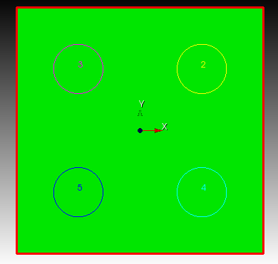
10. Cut the first hole out of the large surface.
On the command bar, select the geometry construction module (Mode - Geometry, Entity - Surface, Action - Boolean).
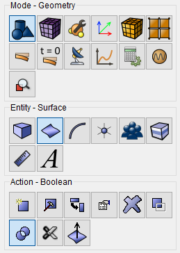
From the list of operations, select Subtract.
Set the following parameters:
A Surface ID(s): 1 (surfaces from which others will be subtracted surfaces);
B Surface ID(s): 2 (surfaces that will be subtracted).
Click Apply.
11. Cut a second hole from the large surface.
From the list of operations, select Subtract.
Set the following parameters:
A Surface ID(s): 6 (surfaces from which others will be subtracted surfaces);
B Surface ID(s): 3 (surfaces that will be subtracted).
Click Apply.
12. Cut a third hole from the large surface.
From the list of operations, select Subtract.
Set the following parameters:
A Surface ID(s): 7 (surfaces from which others will be subtracted surfaces);
B Surface ID(s): 4 (surfaces that will be subtracted).
Click Apply.
11. Cut a fourth hole from the large surface.
From the list of operations, select Subtract.
Set the following parameters:
A Surface ID(s): 8 (surfaces from which others will be subtracted surfaces);
B Surface ID(s): 5 (surfaces that will be subtracted).
Click Apply.
1. On the command bar, select the surface mesh module (Mode - Mesh, Entity - Surface, Action - Intervals).
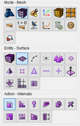
Set the following parameters:
Approximate Size;
Select Surfaces: 9;
Approximate Size 0.04.
Click Apply.
2. Select a meshing scheme.
On the command bar, select the module for constructing a surface mesh (Mode — Mesh, Entity — Surface, Action — Mesh).
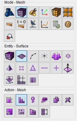
Set the following parameters:
Select a meshing scheme: Automatically Calculate;
Select Surfaces: 9.
Click Apply Scheme.
Click Mesh.
1. Create the material.
In the command bar, select the module for specifying material properties (Mode - Material, Entity - Materials Management).

Specify the material name material1. Go to the Elasticity section and drag from the left column the inscription Isotropic Material to the Material Properties column.
Set the following parameters:
Young's modulus: 2e+11;
Poisson ratio: 0.3.
In the window on the left, go to the General section and drag Density to the window Material properties.
Enter value:
Density: 7800.
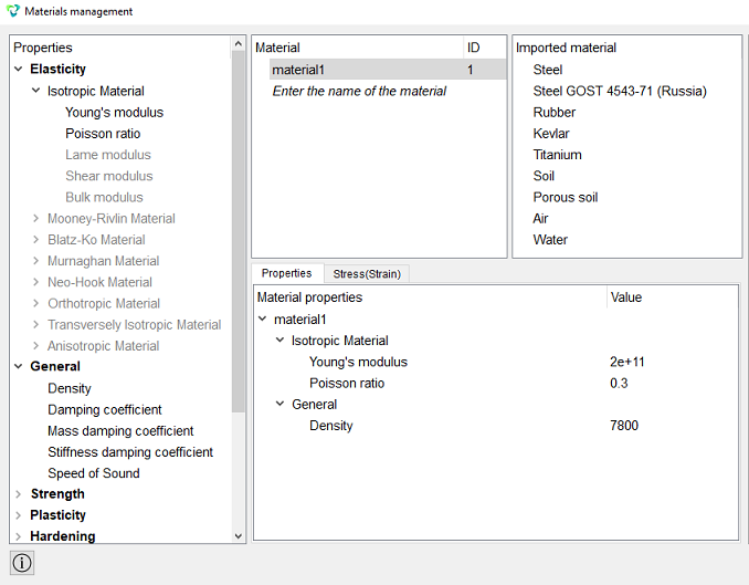
Click Apply.
Close the Materials management window.
2. Create the block.
On the command bar, select the block management module (Mode - Blocks, Entity - Block, Action - Add).

Set the following parameters:
Block Name: pov;
Entity List: Surface;
Entity ID(s): 9.
Click Apply.
3. Set the block parameters.
On the command bar, select the block management module (Mode - Blocks, Entity - Block, Action - Block properties/parameters).

Set the following parameters:
Block Name: pov;
Category: Shell;
Coordinate System: Global Cartesian;
Order: 1.
Set the shell properties, to do this, click on the button  .
.
Set the following parameters:
Material: material1;
Thickness: 0.5;
Eccentricity: 0.5.
Click Apply.
Close the Set Shell Properties window.
Click Apply.
1. Create the first free vertex.
On the command bar, select the module for constructing volumetric geometry (Mode - Geometry, Entity- Vertex, Action - Create).
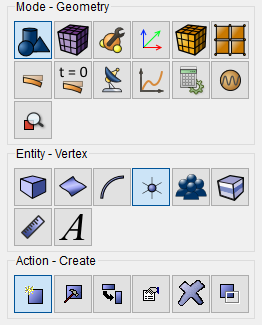
From the drop-down list, select Coordinates.
Set the following parameters:
X Coordinate: 0.25;
Y Coordinate: 0.25;
Create On: Curve.
Click Apply.
2. Create a second free vertex.
From the drop-down list, select Coordinates.
Set the following parameters:
X Coordinate: -0.25;
Y Coordinate: 0.25;
Create On: Curve.
Click Apply.
3. Create a third free vertex.
From the drop-down list, select Coordinates.
Set the following parameters:
X Coordinate: 0.25;
Y Coordinate: -0.25;
Create On: Curve.
Click Apply.
4. Create a fourth free vertex.
From the drop-down list, select Coordinates.
Set the following parameters:
X Coordinate: -0.25;
Y Coordinate: -0.25;
Create On: Curve.
Click Apply.
1. Create a mesh on the vertices.
On the command bar, select the module for constructing a surface mesh (Mode — Mesh, Entity — Vertex, Action — Mesh).
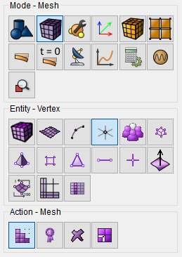
Set the following parameters:
Mesh;
Vertex ID(s): 17 15 16 14.
Click Mesh.
1. Define an entity-distance relationship between vertices and curves.
On the command panel, select the boundary conditions module (Mode - Boundary Conditions, Entity - Cooping Constrain, Action - Create).
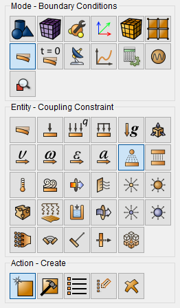
Set the following parameters:
Auto selection of the nearest pairs;
Main Entity: Entity List: Volume;
Entity(s) ID: 1;
Slave Entity: Entity List: Volume;
Entity(s) ID: 2;
Search Distance: 0.11.
Click Apply.
The search distance parameter (tolerance) determines at what distance from the main entity node there must be secondary entity nodes so that get in touch.
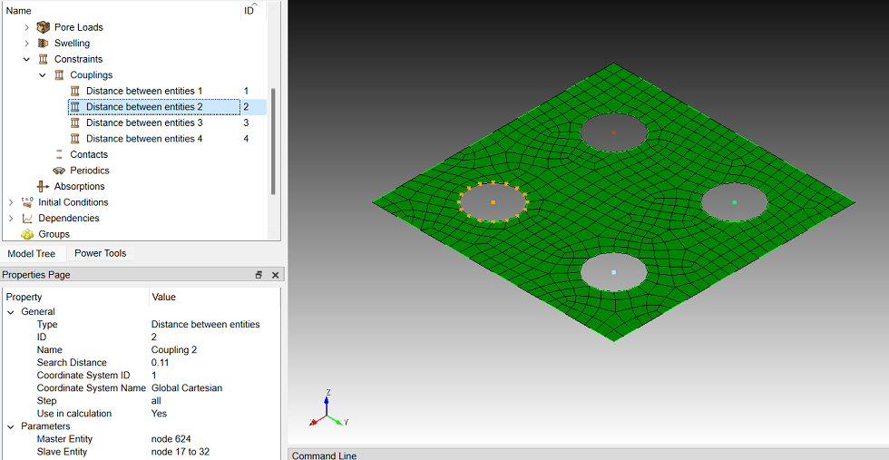
2. Fix vertex 1 for all movements and rotations.
On the command panel, select the boundary conditions module (Mode - Boundary Conditions, Entity - Move, Action - Create).

Set the following parameters:
Entity List: Curve;
Entity ID(s): 1 3;
Degrees of Freedom: All;
DOF Value: 0.
Click Apply.
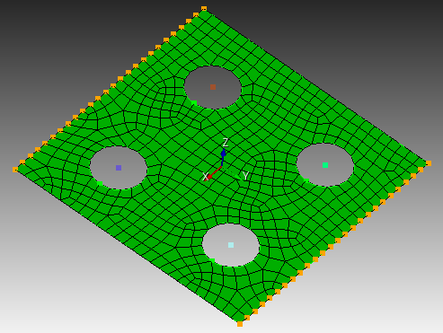
3. Apply force and moment.
On the command panel, select the boundary conditions module (Mode - Boundary Conditions, Entity - Force, Action - Create).
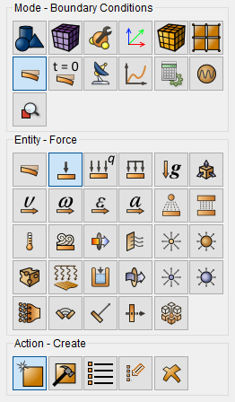
Set the following parameters:
Force Entity List: Node;
Entity ID(s): 1;
Specify Using Vector;
Vector: Force Z Component: 1е6.
Click Apply.
1. Set the type of the problem to be solved.
On the command bar, select the calculation settings module (Mode - Calculation Settings, Calculation Settings - Static, Static - General).

Select:
Dimension: 3D;
Model: Elasticity.
Click Apply.
2. Set the output fields that will display the calculation results.
On the command bar, select the calculation settings module (Mode - Calculation Settings, Calculation Settings - Static, Static - Output Fields).
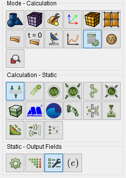
Select:
Calculate nodal and reaction forces;
Output results in 3D view (for beams and shells);
Output Static or Preload intermediate results;
Output intermediate results every (substeps): 1.
Click Apply.
Click Start calculation.
3. In a pop-up window select a folder to save the result and enter the file name.
4. In the case of a successful calculation, the console displays the message: Calculation finished successfully at "date" "time".
1. Open the file with the results. There are three ways to do that.
Click Ctrl+E.
From the main menu, select Calculation. Click Open Results.
Select Results on Command Panel (Mode - Results). Click Open results.

The FidesysViewer window will appear in which you can view with the calculation results.
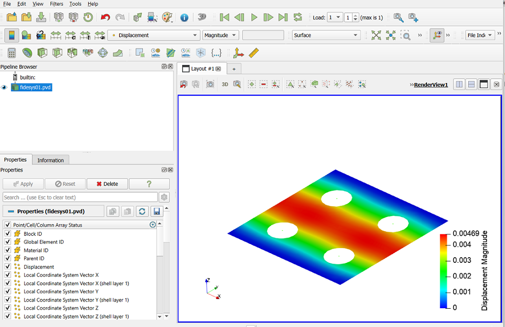
2. Display the Warp By Vector filter.
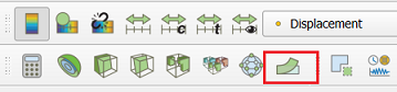
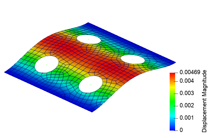
In the Deform By Vector filter in the Properties tab set parameters:
Vectors: Displacement;
Scale Factor: 20;
Representation: Surface With Edges.
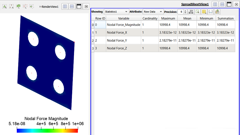
3. Display the nodal force.
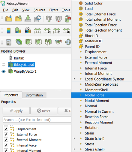
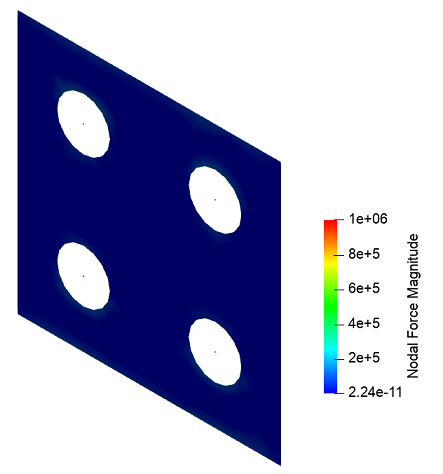
4. Display the nodal force at the point.
Using the Interactive Interactive Select Points On function  select a node on the docked side.
In the standard line, select Filters - Alphabetical - Statistics.
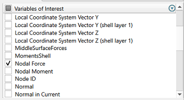
Select Nodal Force.
Click Apply.
Geometry creating, meshing, setting boundary conditions and materials can be performed using the console interface. Below is a link to the program code that allows you to perform the steps described above manual, you only need to specify the full path and name.