Search the documentation
Enter at least 2 characters
Enter at least 2 characters
 |
CAE Fidesys 9.0 Documentation |
An example of the static calculation of a cantilever beam is considered.
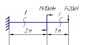
The model is rigidly fixed at one edge. The beam is acted upon by a force F=20kN and moment M=10kNm. Material parameters: Young's modulus E = 2e+11 Pa, coefficient Poisson n = 0.3, density r = 7800 kg/m3.
1. Create reference lines for the future beam.
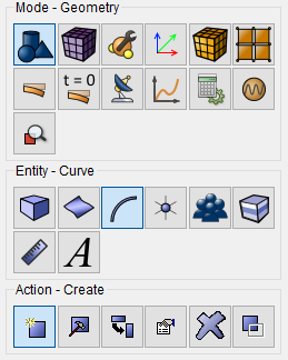
On the command bar, select the module for constructing volume geometry (Mode - Geometry, Entity - Curve, Action - Create).
From the list of geometric primitives, select Line.
Set the following parameters:
Build Using: Location and Direction;
Location: 0 0 0;
Direction: 1 0 0;
Length: 2.
Click Apply.
2. Provide the necessary information to create the second line.
From the list of geometric primitives, select Line.
Set the following parameters:
Build Using: Location and Direction;
Location: 2 0 0;
Direction: 1 0 0;
Length: 1.
Click Apply.
3. Merge the vertex on the resulting beams.
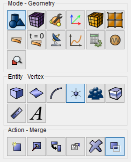
On the command bar, select the geometry construction module (Mode - Geometry, Entity- Vertex, Action - Merge).
Set the following parameters:
Vertex ID(s): all.
Click Apply.
1. On the command bar, select the curve meshing module (Mode — Mesh, Entity — Curve, Action — Mesh).

Specify the required curves:
Select Curves: all;
From the pop-up list, select: Equal.
Approximate Size;
Approximate Size: 0.01.
Click Apply.
Click Mesh.
1. Create a material.
In the command bar, select the module for specifying material properties (Mode —Material, Entity - Materials Management).

In the column "Material" enter the material name material1.
Click Apply.
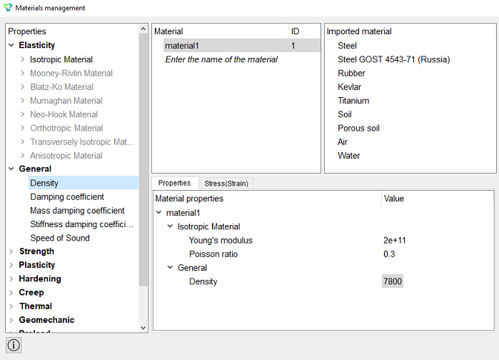
In the Material Properties column, select the created material, then drag the desired properties from the left column to it.
Drag properties and specify their value:
Young's modulus: 2e+11;
Poisson ratio: 0.3;
Density: 7800.
Click Apply.
Close the Materials management window.
2. Create a block for the curve.
On the command bar, select the block management module (Mode - Blocks, Entity - Block, Action - Add).

Set the following parameters:
Block ID: 1;
Block Name: balka;
Entity List: Curve;
Entity ID(s): all.
Click Apply.
3. Set the block parameters.
On the command bar, select the block management module (Mode - Blocks, Entity - Block, Action - Block properties/parameters).

Set the following parameters:
Block Name: balka;
Category: Beam;
Material: material1;
Coordinate System: Global Cartesian;
Order: 1.
Set the properties of the beam, to do this, click on the button  . From the Section profile drop-down list, select Ellipse.
Set the following parameters:
Minor Axis (b): 0.2;
Major Axis (a): 0.2;
Y Eccentricity: 0;
Z Eccentricity: 0.
Click Apply.
Close the Set Beam Properties window.
Click Apply.
1. Secure vertex 1 for all movements and rotations.
On the command panel, select the boundary conditions module (Mode - Boundary Conditions, Entity - Displacement, Action - Create)

Set the following parameters:
Entity List: Vertex;
Entity ID(s): 1;
Degrees of Freedom: All;
DOF Value: 0.
Click Apply.
2. Apply force and moment at node 4.
On the command panel, select the boundary conditions module (Mode - Boundary Conditions, Entity - Force, Action - Create).
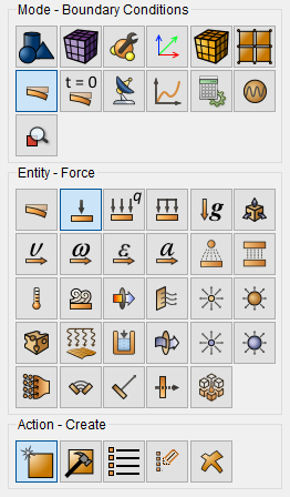
Set the following parameters:
Force Entity List: Vertex;
Entity ID(s): 4;
Specify Using Vector;
Vector: Force Z Component: 20000.
Click Apply.
3. Apply moment at node 2.
Set the following parameters:
Force Entity List: Vertex;
Entity ID(s): 2;
Specify Using Vector;
Vector: Moment Y Component: -10000.
Click Apply.
1. Specify the type of problem you want to solve.
On the command bar, select the calculation settings module (Mode - Calculation Settings, Calculation Settings - Static, Static - General).

Select:
Dimension: 3D;
Model: Elasticity.
Click Apply.
2. Set the output fields that will display the calculation results.
On the command bar, select the calculation settings module (Mode - Calculation Settings, Calculation Settings - Static, Static - Output Fields).
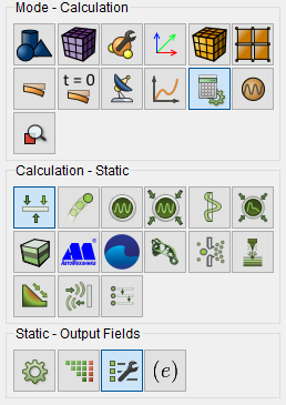
Select:
Calculate nodal and reaction forces;
Output results in 3D view (for beams and shells);
Output Static or Preload intermediate results;
Output intermediate results Every (substeps): 1.
Click Apply.
Click Start calculation.
3. In a pop-up window select a folder to save the result and enter the file name.
4. In the case of a successful calculation, the console displays the message: Calculation finished successfully at "date" "time".
1. Open the file with the results. There are three ways to do that.
Click Ctrl+E.
From the main menu, select Calculation. Click Open Results.
Select Results on Command Panel (Mode - Results). Click Open results.

The FidesysViewer window will appear, in which you can view the calculation results.
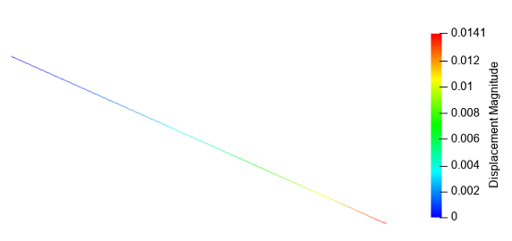
2. Select the finite elements to plot the diagram.
Before running the filter, you need to select the required elements of the model. You need to select cells, the cells must be linear finite elements.
Using the Select Cells Through function, select the beam with a frame.

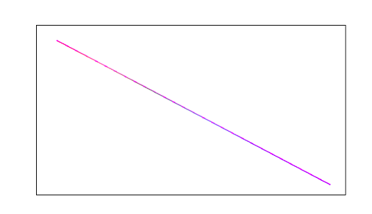
3. Plot the diagram of internal shear forces Q.
Select a filter from the toolbar Plot Internal Resultant Diagram.

In the Properties tab, set the following parameters:
Array Name To Process – Internal Force (Local);
Array Component To Process Transverse Along Z;
Diagram Height – 1;
Diagram Direction – 0 1 0 .
In the Array Name To Process tab, you can select the diagram to plot from the drop-down list: Internal Force or Internal Moment.
In the Array Component To Process tab, from the drop-down list you can select the component of force or moment to plot: longitudinal or transverse for force, and bending or torsional for moment.
Using the Diagram Height and Diagram Direction functions, you can adjust the height and direction of the diagrams if they overlap and intersect.
The diagrams are constructed in a plane defined by two vectors. The first vector is always directed along the beam axis, the second is defined by the user in the Diagram Direction field.
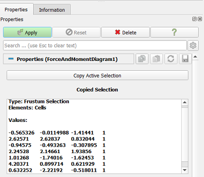
Click Apply.
Below, on the Display tab, set the coloring to match the selected diagram, set the following parameters: Internal Force (Local)_(diagrams) – Transverse Around Z.
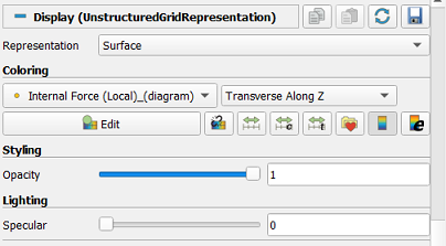
Click Apply.
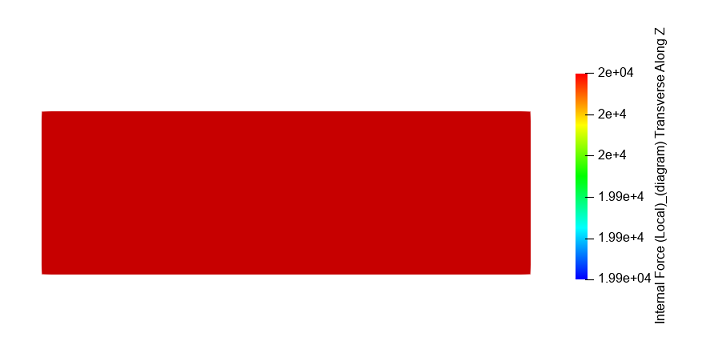
Forces are displayed in N.
4. Build a diagram of internal bending moments M.
On the Properties tab, set the following parameters:
Array Name To Process - Internal Moment (Local);
Array Component To Process - Bending Around Y;
Diagram Height - 1;
Diagram Direction - 0 1 0 .
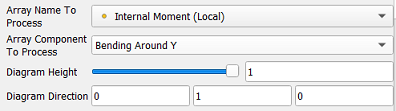
Click Apply.
Below, on the Display tab, set the following parameters: Internal Moments (Local)_(diagrams) – Bending Around Y.
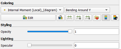
Click Apply.
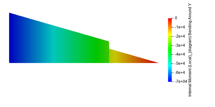
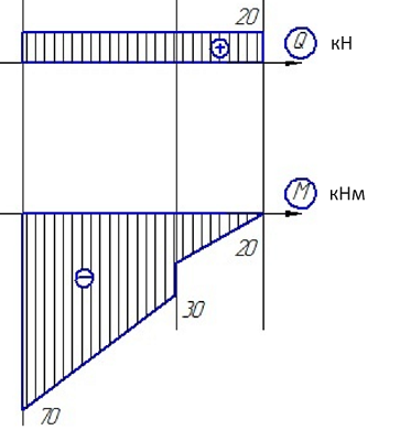
Moments are displayed in N*m. The diagrams of internal transverse forces and bending moments correspond to the analytical data below.
Geometry creating, meshing, setting boundary conditions and materials can be performed using the console interface. Below is a link to the program code that allows you to perform the steps described above manual, you only need to specify the full path and name.