Search the documentation
Enter at least 2 characters
Enter at least 2 characters
 |
CAE Fidesys 9.0 Documentation |
1. Create a circle with radius 1.
On the command bar, select the module for constructing surface geometry (Mode - Geometry, Entity - Surface, Action - Create).

From the list of geometric primitives, select Circle.
Set block parameters:
Specify Circle Using: Radius;
Radius: 1;
Location: ZPlane.
Click Apply.
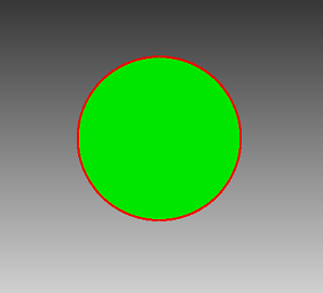
2. Create 3 more such circles.
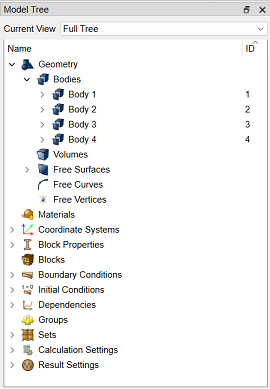
3. Move the first circle.
On the command bar, select the module for constructing surface geometry (Mode - Geometry, Entity - Surface, Action - Transform).
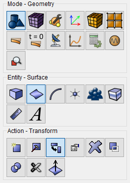
From the pop-up list, select Move.
Set parameters:
Surface ID(s): 1;
Include Merged;
Select Method: To Coordinates;
X: 1;
Y: 1;
Z: 0.
Click Apply.
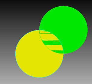
4. Move the second circle.
On the command bar, select the module for constructing surface geometry (Mode - Geometry, Entity - Surface, Action - Transform).
From the pop-up list, select Move.
Set parameters:
Surface ID(s): 2;
Include Merged;
Select Method: To Coordinates;
X: -1;
Y: 1;
Z: 0.
Click Apply.
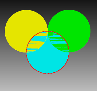
5. Move the third circle.
On the command bar, select the module for constructing surface geometry (Mode - Geometry, Entity - Surface, Action - Transform).
From the pop-up list, select Move.
Set parameters:
Surface ID(s): 3;
Include Merged;
Select Method: To Coordinates;
X: -1;
Y: -1;
Z: 0.
Click Apply.
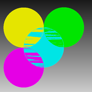
6. Move the fourth circle.
On the command bar, select the module for constructing surface geometry (Mode - Geometry, Entity - Surface, Action - Transform).
From the pop-up list, select Move.
Set parameters:
Surface ID(s): 4;
Include Merged;
Select Method: To Coordinates;
X: 1;
Y: -1;
Z: 0.
Click Apply.

1. Set the mesh parameters. On the command bar, select the build module surface mesh (Mode - Mesh, Entity- Surface, Action – Mesh).
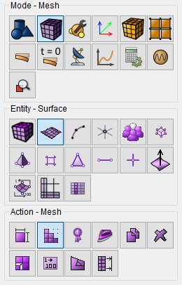
From the pop-up list, select Trimesh.
Select Surfaces: all.
Use Geometry Sizing.
Click Apply Scheme.
2. Build a mesh. On the command bar, select the surface plotting module mesh (Mode - Mesh, Entity - Surface, Action - Intervals).
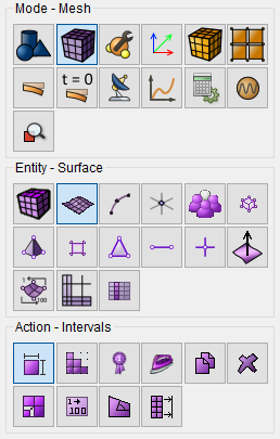
From the drop-down list, select Automatic Sizing.
Select Surfaces: all.
Auto Factor: 3.
Click Apply Size.
Click Mesh.
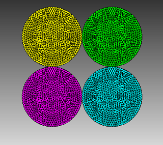
1. Create a material.
In the command bar, select the module for specifying material properties (Mode —Material, Entity - Materials Management).

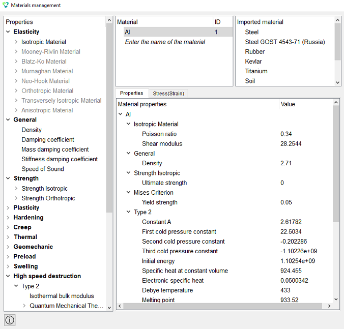
In the Material Management widget that opens, in the middle column, specify material name Al.
In the properties column, open the Elasticity section and from the Isotropic Material drag the following parameters into the Material Properties column:
Poisson ratio: 0.34;
Shear modulus: 28.2544.
Open the General section and drag the title Density in the Material Properties column.
Set the following parameters:
Density: 2.71.
Open the Strength section and from the Strength Isotropic drag the following parameters into the Material Properties column:
Ultimate strength: 0.
Open the section Plasticity and from the subsection Mises Criterion drag the following parameters into the Material Properties column:
Yield strength: 0.05.
Open the High speed destruction section and from the Type 2 drag the following parameters into the Material Properties column:
Constant A: 2.61782;
First cold pressure constant: 22.5034;
Second cold pressure constant: -0.202286;
Third cold pressure constant: -1.10226e+09;
Initial energy: 1.10254e+09;
Specific heat at constant volume: 924.455;
Electronic specific heat : 0.0500342;
Debye temperature: 433;
Melting point: 933.52.
Then from the Type 2 section and the Quantum Mechanical Theory to the Material Properties column
drag the following parameters:
Landau-Slater theory: 0.
Open the High speed destruction section and from the Type 4 drag the following parameters into the Material Properties column:
Speed of sound: 5.333;
Experimental tangent: 1.356.
Open the High speed destruction section and from the subsection Failure criteria drag the following into the Material Properties column parameters:
Ultimate strength: 1;
Ultimate overstress: 0.15;
Ultimate strain: 0.32;
Ultimate compression strain: 1;
Ultimate shear strain: 0.385.
Click Apply.
2. Specify the second material.
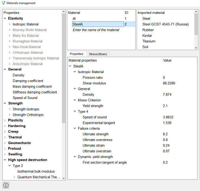
In the Material Management widget that opens, in the middle column, specify material name SteelA.
In the properties column, open the Elasticity section and from the subsection Isotropic Material into the Material Properties column, drag the following parameters:
Poisson ratio: 0;
Shear modulus: 88.2286.
Open the General section and drag the title Density to the Material Properties column.
Set the following parameters:
Density: 7.874.
Open the section Plasticity and from the subsection Mises Criterion drag the following parameters into the Material Properties column:
Yield strength: 2.1.
Open the High speed destruction section and from the Type 4 drag the following parameters into the Material Properties column:
Speed of sound: 3.9832;
Experimental tangent: 1.536.
Open the High speed destruction section and from the subsection Failure criteria drag the following into the Material Properties column parameters:
Ultimate strength: 8.2;
Ultimate overstress: 0.8;
Ultimate strain: 0.24;
Ultimate overstrain: 0.07.
Open the High speed destruction section and from the Dynamic yield strength to the Material Properties column, drag the following parameters:
First section tangent of angle: 0.2.
Click Apply.
3. Specify the third material.
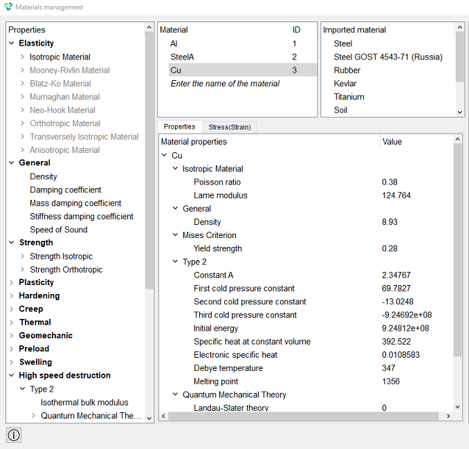
In the Material Management widget that opens, in the middle column, specify material name Cu.
In the properties column, open the Elasticity section and from the subsection Isotropic Material into the Material Properties column, drag the following parameters:
Poisson ratio: 0.38;
Lame modulus: 124.764.
Open the General section and drag the title Density in the Material Properties column. Set the following parameters:
Density: 8.93.
Open the section Plasticity and from the subsection Mises Criterion drag the following parameters into the Material Properties column:
Yield strength: 0.28.
Open the High speed destruction section and from the Type 2 drag the following parameters into the Material Properties column:
Constant A: 2.34767;
First cold pressure constant: 69.7827;
Second cold pressure constant: -13.0248;
Third cold pressure constant: -9.24692e+08;
Initial energy: 9.24812e+08;
Specific heat at constant volume: 392.522;
Electronic specific heat: 0.0108583;
Debye temperature: 347;
Melting point: 1356.
Then from the Type 2 section and the Quantum Mechanical Theory to the Material Properties column
drag the following parameters:
Landau-Slater theory: 0.
Open the High speed destruction section and from the subsection Failure criteria drag the following into the Material Properties column parameters:
Ultimate strength: 0.45;
Ultimate strain: 0.4.
Click Apply.
4. Specify the fourth material.
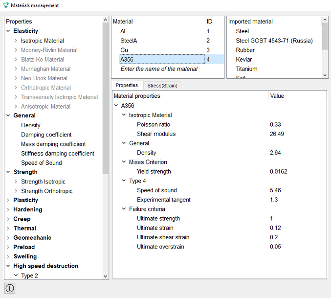
In the Material Management widget that opens, in the middle column, specify material name A356.
In the properties column, open the Elasticity section and from the subsection Isotropic Material into the Material Properties column, drag the following parameters:
Poisson ratio: 0.33;
Shear modulus: 26.49.
Open the General section and drag the title Density in the Material Properties column. Set the following parameters:
Density: 2.64.
Open the section Plasticity and from the subsection Mises Criterion drag the following parameters into the Material Properties column:
Yield strength: 0.0162.
Open the High speed destruction section and from the Type 4 drag the following parameters into the Material Properties column:
Speed of sound: 5.46;
Experimental tangent: 1.3.
Open the High speed destruction section and from the subsection Failure criteria drag the following into the Material Properties column parameters:
Ultimate strength: 1;
Ultimate strain: 0.12;
Ultimate shear strain: 0.2;
Ultimate overstrain: 0.05.
Click Apply.
Close the Material management window.
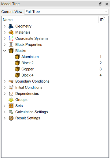
5. Create the first block. On the command bar, select the control module blocks (Mode - Blocks, Entity - Block, Action - Add).

Set the following parameters:
Block ID: 1;
Entity List: Surface;
Entity ID(s): 1.
Click Apply.
6. Create a second block. On the command bar, select the control module blocks (Mode - Blocks, Entity - Block, Action - Add).
Set the following parameters:
Block ID: 2;
Entity List: Surface;
Entity ID(s): 2.
Click Apply.
7. Create a third block. On the command bar, select the control module blocks (Mode - Blocks, Entity - Block, Action - Add).
Set the following parameters:
Block ID: 3;
Entity List: Surface;
Entity ID(s): 3.
Click Apply.
8. Create a fourth block. On the command bar, select the control module blocks (Mode - Blocks, Entity - Block, Action - Add).
Set the following parameters:
Block ID: 4;
Entity List: Surface;
Entity ID(s): 4.
Click Apply.
9. Set the parameters of the first block.
On the command bar, select the block control module (Mode - Blocks, Entity - Block, Action - Block Properties/parameters).

Set the following parameters:
Block ID(s): 1;
Category: Plane;
Material: Al;
Coordinate System: Global Cartesian;
Order: 1.
Click Apply.
10. Set the parameters of the second block.
On the command bar, select the block control module (Mode - Blocks, Entity - Block, Action - Block Properties/parameters).
Set the following parameters:
Block ID(s): 2;
Category: Plane;
Material: SteelA;
Coordinate System: Global Cartesian;
Order: 1.
Click Apply.
11. Set the parameters of the third block.
On the command bar, select the block control module (Mode - Blocks, Entity - Block, Action - Block Properties/parameters).
Set the following parameters:
Block ID(s): 3;
Category: Plane;
Material: Cu;
Coordinate System: Global Cartesian;
Order: 1.
Click Apply.
12. Set the parameters of the fourth block.
On the command bar, select the block control module (Mode - Blocks, Entity - Block, Action - Block Properties/parameters).
Set the following parameters:
Block ID(s): 4;
Category: Plane;
Material: A356;
Coordinate System: Global Cartesian;
Order: 1.
Click Apply.
1. Set the initial velocity of the first surface.
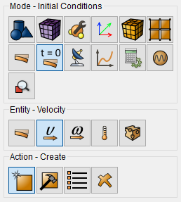
On the command bar, select the module for setting initial conditions (Mode - Initial Conditions, Entity- Velocity, Action - Create).
Set the following parameters:
Entity List: Surface;
Entity ID(s): 1;
X-Translation: -0.5;
Y-Translation: -0.5.
Click Apply.
2. Set the initial velocity of the second surface.
Set the following parameters:
Entity List: Surface;
Entity ID(s): 2;
X-Translation: 0.5;
Y-Translation: -0.5.
Click Apply.
3. Set the initial velocity of the third surface.
Set the following parameters:
Entity List: Surface;
Entity ID(s): 3;
X-Translation: 0.5;
Y-Translation: 0.5.
Click Apply.
4. Set the initial velocity of the fourth surface.
Set the following parameters:
Entity List: Surface;
Entity ID(s): 4;
X-Translation: -0.5;
Y-Translation: 0.5.
Click Apply.

1. Set the solver parameters.
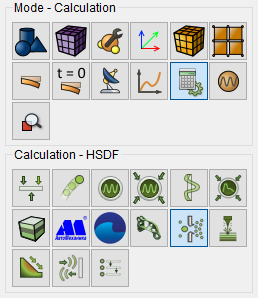
On the command bar, select the calculation settings module (Mode - Calculation Settings, Calculation Settings - HSDF).
Select:
Dimension: 2D;
Import Object Yype: MEDIT (.mesh);
Max Time: 5.01;
Time Step: 1.0.
Click Apply.
Click Start Calculation.
2. In a pop-up window select a folder to save the result and enter the file name.
3. In the case of a successful calculation, the console displays the message: Calculation finished successfully at "date" "time".
1. Open the file with the results. There are three ways to do that.
Click Ctrl+E.
From the main menu, select Calculation. Click Open Results.
Select Results on Command Panel (Mode - Results). Click Open results.

The FidesysViewer window will appear, in which you can view the calculation results.
2. In the standard line, select Filters - Alphabetical - Warp By Vector.
Set the following parameters:
Vectors: Displacement;
Scale Factor: 1.
Click Apply.
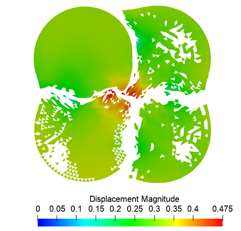
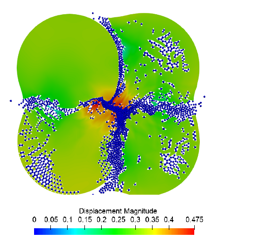
3. In the standard line, select Filters - Alphabetical - Glyph.
Set the following parameters:
Glyph Type: Sphere;
Orientation Array: Displacement;
Scale Array: ball.
Click Apply.
Geometry creating, meshing, setting boundary conditions and materials can be performed using the console interface. Below is a link to the program code that allows you to perform the steps described above manual, you only need to specify the full path and name.