Search the documentation
Enter at least 2 characters
Enter at least 2 characters
 |
CAE Fidesys 9.0 Documentation |
The example describes how to calculate the natural frequencies of a duct for predicting the acoustic response of the air volume of the duct, which can be used to evaluate the performance of silencers (acoustic filters).
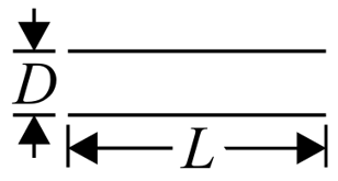
Natural frequencies of the undamped volume of the pipe and cylindrical air duct under free boundary conditions can be calculated using the formula:

where n is the mode index (1, 2, 3 ...), c0 is the speed of sound, L - length of air volume.
1. Create a cylinder.
On the command bar, select the module for constructing volume geometry (Mode - Geometry, Entity - Volume, Action - Create).
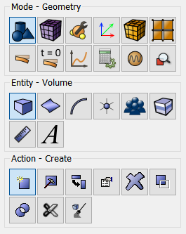
From the list of geometric primitives, select Cylinder.
Specify the required parameters:
Height: 3;
Section: Circular;
Radius: 0.05.
Click Apply.
2. Make a webcut the coordinate plane.
On the command bar, select the module for constructing volume geometry (Mode - Geometry, Entity - Volume, Action - Webcut).
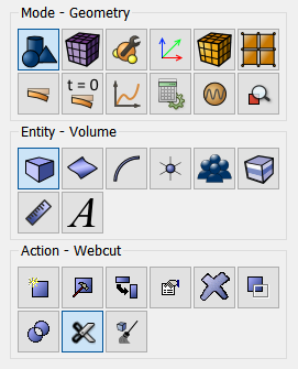
From the list of possible types of sections, select Coordinate Plane.
Set the following parameters:
Volume ID(s): all (volume that will be cut);
Cut: YZ plane;
Offset Value: 0.
Click Apply.
3. Make the cut again.
Set the following parameters:
Volume ID(s): all (volume that will be cut);
Cut: ZX plane;
Offset Value: 0.
Click Apply.
4. Merge the geometry.
On the command bar, select the module for constructing volume geometry (Mode - Geometry, Entity - Volume, Action - Imprint and Merge).
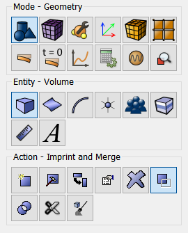
From the list, select: Merge Volumes.
Set the following parameters:
Volume ID(s): all.
Click Apply.
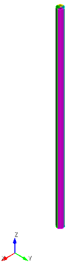
1. Create a mesh on curves 19 30 29 34 36 21 16 44.
On the command bar, select the mesh module (Mode — Mesh, Entity — Curve, Action — Mesh).
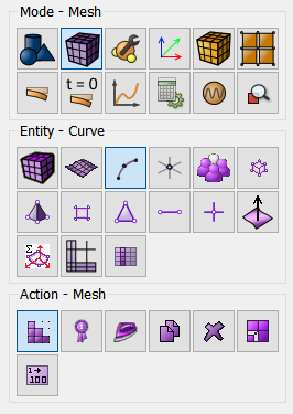
Specify the required parameters:
Select Curves: 19 30 29 34 36 21 16 44;
Select the mesh construction method: Equal;
Select a meshing scheme: Interval;
Interval: 6.
Click Apply Size.
Click Mesh.
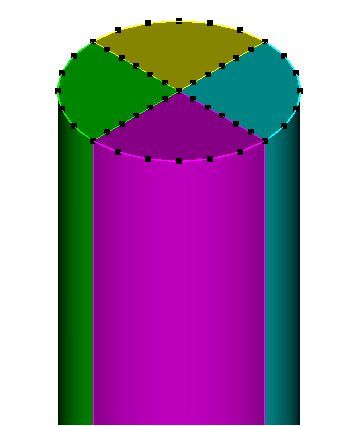
2. Create a mesh on the surfaces.
On the command bar, select the surface mesh module (Mode — Mesh, Entity – Surface, Action – Intervals).
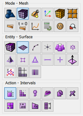
Please specify:
Select a meshing scheme: Automatic Sizing;
Select Surfaces: 20 28 26 14.
Click Apply Size.
Click Mesh.
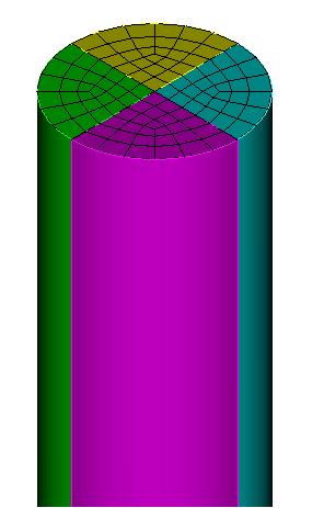
3. Create a mesh on the curves 3 33 15 17 5.
On the command bar, select the mesh module (Mode — Mesh, Entity — Curve, Action — Mesh).
Specify the required parameters:
Select Curves: 3 33 15 17 5;
Select the mesh construction method: Equal;
Select a mesh design: Approximate Size;
Approximate Size: 0.25.
Click Apply Size.
Click Mesh.
4. Create a mesh on the volumes.
On the command bar, select the volume mesh module (Mode — Mesh, Entity - Volume, Action - Mesh).
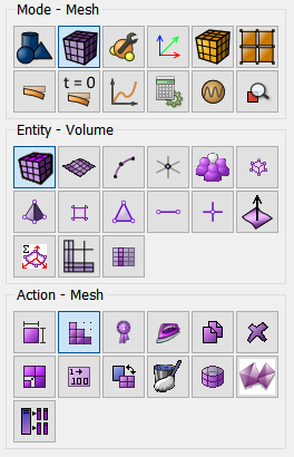
From the drop-down list, select: Sweep.
Set the following parameters:
Select Volumes: all.
Click Apply Scheme.
Click Mesh.
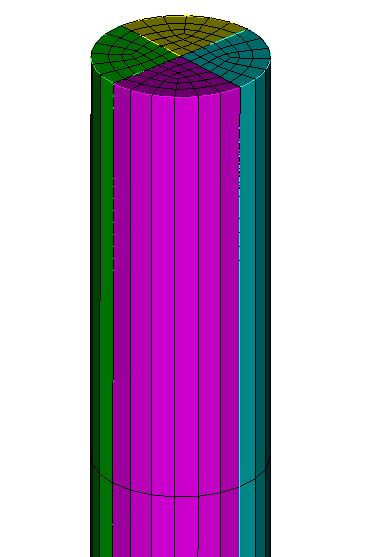
1. Create the material.
In the command bar, select the module for specifying material properties (Mode — Material, Entity — Materials Management).
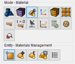
In the Manage Materials window that opens, in the second column, click on the inscription with the mouse. Specify the name of the material and write “MAT1”.
Click ENTER.
In the left column, select General and while holding the left mouse button, drag the Density label to Material Properties. Twice click in the Value field opposite Density and specify the number 1.21. Similarly, from the General section, add Speed of Sound - 343.
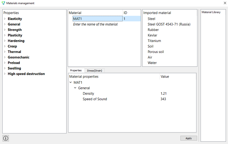
Click Apply.
Close the Material management window.
2. Create a block of one material type.
On the command bar, select the block management module (Mode — Blocks, Entity — Block, Action — Add).
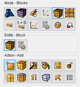
Set the following parameters:
Block ID: 1;
Entity List: Volume;
Entity ID(s): all.
Click Apply.
3. Set block parameters.
On the command bar, select the block management module (Mode - Blocks, Entity - Block, Action - Block properties/parameters).
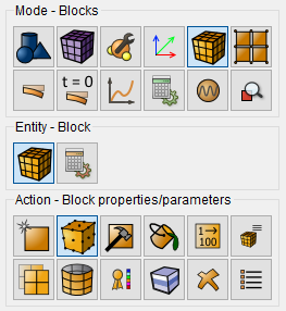
Set the following parameters:
Block ID(s): 1;
Category: Fluid;
Material: MAT1;
Order: 2.
Click Apply.
1. Specify the type of problem you want to solve.
On the command bar, select the calculation settings module (Mode - Calculation Settings, Calculation Settings - Mode Frequency Analysis, Modal Frequency - General).
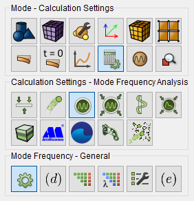
Set the following settings:
Dimension: 3D;
Number of Eigenmodes: 6.
Click Apply.
Click Start Calculation.
2. In a pop-up window select a folder to save the result and enter the file name.
3. In the case of a successful calculation, the console displays the message: Calculation finished successfully at "date" "time".
4. After the calculation is completed, the results will appear on the command line:
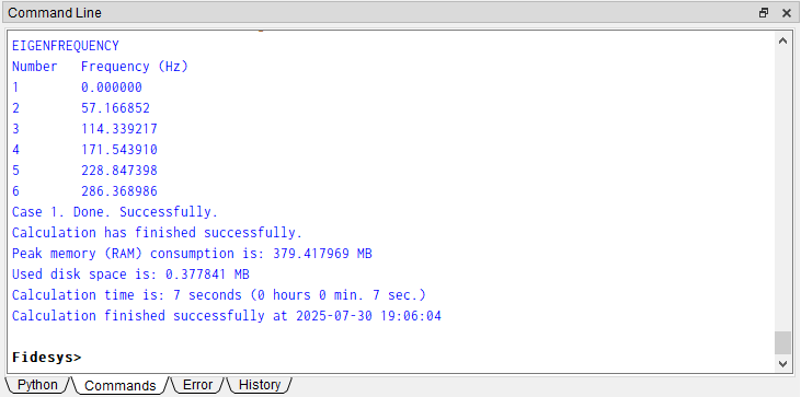
1. The table shows a comparison of the values of the calculated eigenfrequency of CAE Fidesys with elements of the first and second orders and theoretically (according to the presented formula)::
Number, n |
Theoretical eigenfrequency, Hz |
CAE Fidesys
eigenfrequency |
Error, % |
CAE Fidesys
eigenfrequency |
Error, % |
0 |
0.00 |
0.00 |
0.00 |
||
1 |
57.17 |
57.33 |
0.28 |
57.17 |
0.0 |
2 |
114.33 |
115.64 |
1.13 |
114.34 |
0.01 |
3 |
171.50 |
175.93 |
2.52 |
171.54 |
0.02 |
4 |
228.67 |
239.20 |
4.40 |
228.85 |
0.08 |
5 |
285.83 |
306.39 |
6.71 |
286.37 |
0.19 |
The table shows a good agreement between the first natural frequencies and the theoretical ones even on a fairly large grid. It is also possible to draw conclusions about rationality selection of rational density of the finite element mesh depending on on the index of the mode that needs to be determined.
2. Open the file with the results. There are three ways to do that.
Click Ctrl+E.
From the main menu, select Calculation. Click Open Results.
Select Results on Command Panel (Mode - Results). Click Open results.
The FidesysViewer window will appear, in which you can view the calculation results.
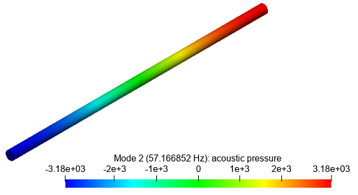
3. Display the component Mode 2 (57.166852 Hz): acoustic pressure. On the toolbar, set the following options:
Display field: Mode 2 (57.166852 Hz): acoustic pressure;
Display type: Surface.
Geometry creating, meshing, setting boundary conditions and materials can be performed using the console interface. Below is a link to the program code that allows you to perform the steps described above manual, you only need to specify the full path and name.