Search the documentation
Enter at least 2 characters
Enter at least 2 characters
 |
CAE Fidesys 9.0 Documentation |
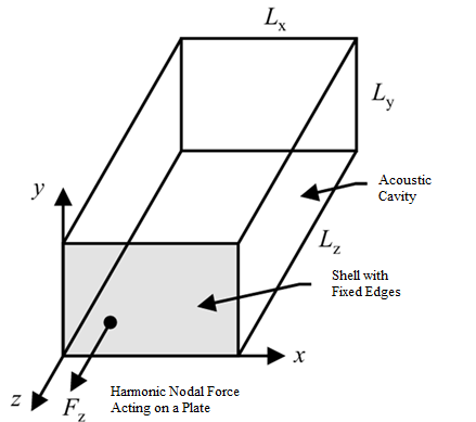
The calculation diagram of the problem is shown in the figure. Coupled calculation is carried out for a parallelepiped acoustic cavity with a flexible simply supported shell. The harmonic force acts on the shell, causing it to vibrate. Vibration of the shell causes acoustic pressure within the acoustic cavity. Geometric dimensions of the model:
Acoustic Cavity width (Lx) 0.5 m;
Acoustic Cavity height (Ly) 0.3 m;
Acoustic Cavity depth (Lz) 1.1 m;
Shell thickness (h) 0.003 м.
Coordinates of the force application point 0.100 m, 0.075 m, 0.000 m, coordinates Acoustic pressure pickup points (sensor) 0.125 m, 0.150 m, -0.-755 m.
1. Create a rectangular brick.
On the command bar, select the module for constructing volume geometry (Mode - Geometry, Entity - Volume, Action - Create).

Select Brick in the list of geometric elements.
Set the brick dimensions:
X (width): 0.5;
Y (height): 0.3;
Z (depth): 1.1.
Click Apply.
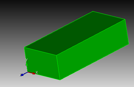
2. Move the volume to the origin.
On the command bar, select the module for constructing volume geometry (Mode - Geometry, Entity - Volume, Action - Transform).
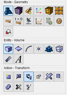
From the list of possible transformation types, select Move.
Set the following parameters:
Volume ID(s): 1;
Select Method: Distance;
X Distance: 0.25.
Y Distance: 0.15;
Z Distance: -0.55.
Click Apply.
1. On the command bar, select the mesh module (Mode - Mesh, Entity - Volume, Action - Intervals).
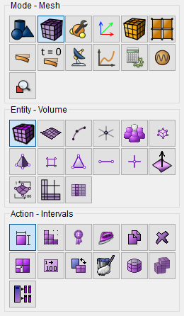
Specify the required parameters:
Approximate Size;
Select Volumes: all;
Approximate Size: 0.025;
Apply Size Before Meshing.
Click Apply Size.
Click Mesh.
1. Create the material.
In the command bar, select the module for specifying material properties (Mode - Material, Entity - Materials Manegment).

In the Manage Materials window that opens, in the second column, click click on the inscription with the mouse. Specify the name of the material and write “Mat1”. Click ENTER key.
In the left column, select General and while holding the left mouse button, drag the Density label to Material Properties. Twice click in the Value field opposite Density and specify the number 1.21. Similarly, from the General section, add Speed of Sound - 344.

Create a second material "Mat2".
In the properties column, open the Elasticity, Isotropic Material list and drag Young's modulus and Poisson ratio to the column Material properties. Similarly, from the General section, add Density and Damping coefficient.
Fill in the properties as follows:
Young's modulus: 7e+10;
Poisson ratio: 0.3;
Density: 2700;
Damping coefficient: 0.001.
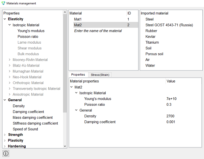
Click Apply.
Close the Materials management window.
3. Create the first block.
On the command bar, select the block management module (Mode - Blocks, Entity - Block, Action - Add).

Set the following parameters:
Block ID: 1;
Entity List: Volume;
Entity ID(s): 1.
Click Apply.
4. Create a second block.
On the command bar, select the block management module (Mode - Blocks, Entity - Block, Action - Add).
Set the following parameters:
Block ID: 2;
Entity List: Surface;
Entity ID(s): 1.
Click Apply.
5. Set the parameters of the first block.
On the command bar, select the block management module (Mode - Blocks, Entity - Block, Action - Block properties/parameters).

Set the following parameters:
Block ID(s): 1;
Category: Fluid;
Material: Mat1;
Order: 2.
Click Apply.
6. Set the parameters of the second block.
On the command bar, select the block management module (Mode - Blocks, Entity - Block, Action - Block properties/parameters).
Set the following parameters:
Block ID(s): 2;
Category: Shell;
Material: Mat2;
Order: 2.
Set the Shell Properties, to do this, click on the button  .
.
Set the following parameters:
Material: Mat2;
Thickness: 0.003;
Eccentricity: 0.5.
Click Apply.
Close the Set Shell Properties window.
Click Apply.
1. Specify a set of nodes.
On the command bar, select the set management module (Mode - Sets, Entity - Nodeset, Action - Create nodeset).
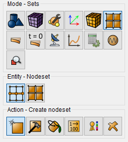
Set the following parameters:
Select: Node;
ID(s): 1.
Click Apply.
1. Set the harmonic force.
On the command bar, select the module for specifying boundary conditions (Mode - Boundary Conditions, Entity - Force, Action - Create).
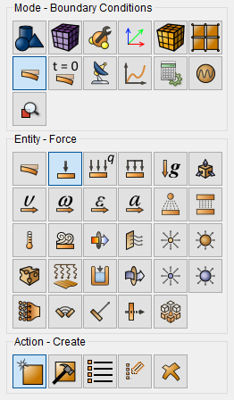
Set the following parameters:
Force Entity List: Nodeset;
Entity ID(s): 1;
Specify Using Vector;
Force X Component: 0;
Force Y Component: 0;
Force Z Component: 1;
Moment X Component: 0;
Moment Y Component: 0;
Moment Z Component: 0.
Click Apply.
2. Set the harmonic character of the force.
On the command bar, select the module for setting BC dependencies (Mode - BC Dependency).
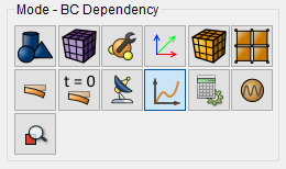
In the BC Dependency window that appears, select Force, go to the Formula.
Set the following parameters:
Harmonic;
Amplitude (A): 1.0.
Click Apply.
3. Set an anchor for the shell.
On the command bar, select the module for specifying boundary conditions (Mode - Boundary Conditions, Entity - Displacement, Action - Create).

Set the following parameters:
Entity List: Curve;
Entity ID(s): 1 2 3 4;
Degrees Of Freedom: X, Y, Z;
Value: 0.
Click Apply.
1. Set the type of the problem to be solved.
On the command bar, select the calculation settings module (Mode - Calculation Settings, Calculation Settings - Frequency Analysis, Frequency Analysis - General).
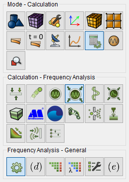
Set the following calculation parameters:
Dimension: 3D;
Number of Eigenmodes: 10;
Lowest;
Method: Mod Superposition;
Frequency Spacing Type: Uniform With Eigen Values;
Frequency Interval: 0 - 400;
Steps Count: 4000.
Click Apply.
Click Start Calculation.
2. In a pop-up window select a folder to save the result and enter the file name.
3. In the case of a successful calculation, the console displays the message: Calculation finished successfully at "date" "time".
1. Open the file with the results. There are three ways to do that.
Click Ctrl+E.
From the main menu, select Calculation. Click Open Results.
Select Results on Command Panel (Mode - Results). Click Open results.

The FidesysViewer window will appear, in which you can view the calculation results.
2. Using the Find Data function, find the node where the microphone recording acoustic pressure.
To do this, on the command bar, click on the Find data matching varios
criteria fro the current source -  .
.
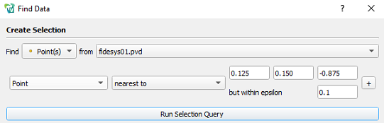
In the “Find Data” window that appears, set the following parameters:
Find: Point(s);
Point;
nearest to: 0.125; 0.150; -0.875;
but within epsilon: 0.1.
Click Run Selected Query.
Click Close the "Find Data" window.
3. Connect the Harmonic Analysis filter. For this purpose in standard line, select Filters - Alphabetical - Harmonic Analysis.
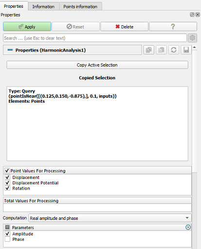
For the Harmonic Analysis filter in the Tree in the Properties tab specify:
Copy Active Selection;
Computation: Real amplitude and phase;
Parameters: Amplitude.
Click Apply.
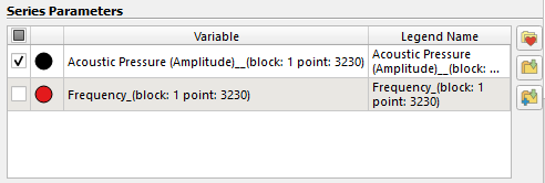
In the Series Parameters section that appears, select only Acoustic Pressure (Amplitude).
Next, in the Left Axis Range section, check the Left Axis Log Scale.

As a result, the desired graph is obtained on the right side of the screen.
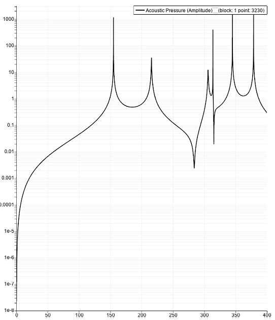
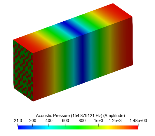
4. Derive the forced form of the acoustic pressure distribution.
To do this, first remove the Harmonic Analysis filter.
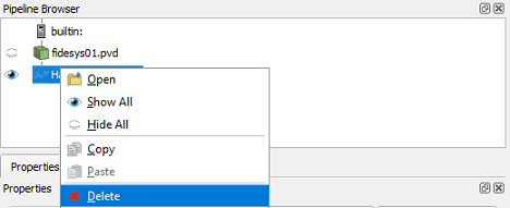
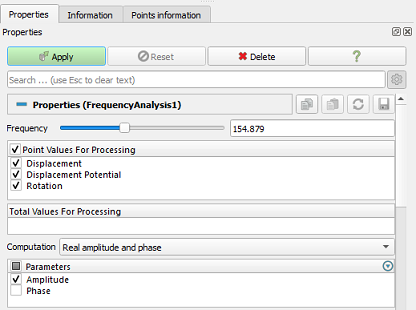
Then connect the Frequency Analysis filter. In the standard line select Filters - Alphabetical - Frequency Analysis.
In the Properties tab, specify:
Frequency: 154.879;
Calculation: Real amplitude and phase;
Parameters: Amplitude.
Click Apply.
Geometry creating, meshing, setting boundary conditions and materials can be performed using the console interface. Below is a link to the program code that allows you to perform the steps described above manual, you only need to specify the full path and name.