Search the documentation
Enter at least 2 characters
Enter at least 2 characters
 |
CAE Fidesys 9.0 Documentation |
Connections by degrees of freedom are most often used either to create hinge connection in models with beams and/or shells, or to create absolutely rigid region (if you do not set the connection rigidity for the selected degrees of freedom). Also, this type of connection can be used instead of final elements of the “spring” type, if for the associated degrees of freedom you specify connection rigidity. Should be considered, that when connecting using this type of connections of nodes that do not lie in the same coordinates in space (as happens when creating a hinge), the connected region will not be able to rotate adequately as a rigid whole, in contrast to a similar region when connected by distance connections.
In the case of connection by degrees of freedom of beams or shells with volumetric elements must remember that volumetric elements do not have rotational degrees of freedom and connection is possible only by displacement.
Distance connections are most often used to transmit torque moment, remote force or remote boundary condition (remote displacement) from the main entity (most often a vertex or node) on the side. This type of communication allows you to take into account the leverage of the remote application load or boundary condition. Suitable for weight load simulation or forces from that part of the structure that is not directly modeled in a specific calculation, but the load from which must be taken into account. Also can be used to create an absolutely rigid region.
When connected using this type of connection, the connected region is able to rotate in space as a rigid whole, in contrast to the binding of a similar region by degrees of freedom. The disadvantage of this type of binding is a number cases is that the resulting hard region adds additional rigidity to the structure.
Interpolation connections (RBE3 type) are most often used for torque transmission, remote force or remote boundary condition (remote displacement) from the main entity (most often vertex or node) to a side one. This type of connection allows you to take into account the leverage application of a remote load or boundary condition without adding to additional rigidity design. Suitable for simulating weight load or force from that part of the structure that is not directly modeled in a specific calculation, but the load from which must be taken into account. In some cases, when combining this type of connection with additional finite elements, can be used to model various connectors, including spot welding.
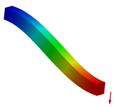
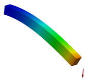
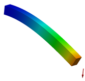
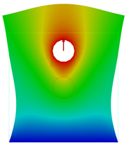
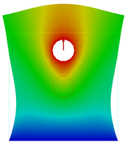
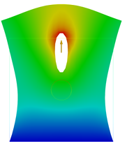
Examples of deformation of structures with different types of connections are given in table 1. From table 1 it can be seen that in the case of a plate with a circular hole the behavior of a structure with connections by distance is close to connections by degrees freedom during deformation. This fact is due to the fact that in both of these In cases where the ring moves linearly and there is no tilt or and rotation of the structure. In the case of beams, on the contrary, due to the coupling by degrees freedom of the main entity (the vertex on which the load is applied) and the secondary (surface of the beam end) the displacement of the nodes of the secondary entity is equal to to move the main entity, which prevents the end from tilting.
Table 1 - Influence of connections on the deformed state of structures, loaded by applying force to the pilot unit, which is connected with part of the structure (beam end and hole ring)
Communication by degrees of freedom |
Distance communication |
Interpolating link |
|
|
|
|
|
|