Search the documentation
Enter at least 2 characters
Enter at least 2 characters
 |
CAE Fidesys 9.0 Documentation |
1. Create a structure from beams (lines).
On the command bar, select the module for constructing geometry (Mode — Geometry, Entity — Curve, Action — Create).
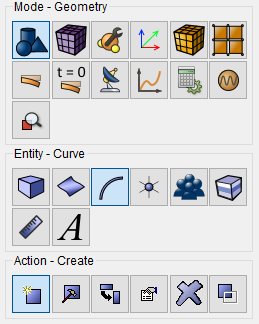
Select Line from the drop-down list. On the Build Using panel, select Location and Direction.
Next, specify the necessary data to create the first line:
Location: 0 0 0 (through a space);
Direction: 0 1 0;
Length: 1.
Click Apply.
2. Specify the necessary data to create the second line:
Location: 0 1 0;
Direction: 1 0 0;
Length: 1.
Click Apply.
3. Specify the necessary data to create the third line:
Location: 1 1 0;
Direction: 0 -1 0;
Length: 1.
Click Apply.
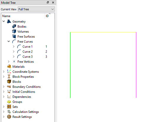
The result is a beam structure. The beams do not have common vertices, because later it is planned to add links to create a hinge at the junction.
1. On the command bar, select the mesh module (Mode — Mesh, Entity - Curve, Action - Mesh).

Set the following parameters:
Select Curves: All;
Equal;
Approximate Size;
Approximate Size: 0.1.
Click Apply Size.
Click Mesh.
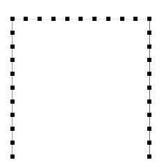
1. Create the material.
In the command bar, select the module for specifying material properties (Mode — Material, Entity — Materials Management).

In the Material Management widget, in the middle column, specify the name of the material material1. In the properties column, open the Elasticity list and drag the name Isotropic Material to the Material Properties column. Fill in the properties as follows:
Young's modulus: 2e+11;
Poisson's ratio: 0.3.
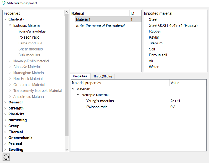
Click Apply.
Close the Materials management window.
2. Create a block of one material type.
On the command bar, select the block management module (Mode — Blocks, Entity — Block, Action — Add).

Set the following parameters:
Block ID: 1;
Entity List: Curve;
Entity ID(s): All.
Click Apply.
3. Set the block parameters.
On the command bar, select the block management module (Mode — Blocks, Entity — Block, Action — Block properties/parameters).

Set the following parameters:
Block ID(s): 1;
Category: Beam;
Material: Material 1;
Coordinate System: Global Cartesian;
Order: 2.
Set the properties of the beam, to do this, click on the button  . From the Section profile drop-down list, select Ellipse.
Set the following parameters:
Minor axis (b): 0.01;
Major axis (a): 0.01.
Click Apply.
Close the window Set Beam Properties.
Click Apply.
1. Anchor vertices A and D across all movements and turns.
On the command panel, select the boundary conditions module (Mode - Boundary Conditions, Entity — Displacement, Action - Create).

Set the following parameters:
Entity List: Vertex;
Entity ID(s): 1 6 (or select the vertices with the mouse while holding down the Ctrl key);
Degrees of Freedom: All;
DOF Value: 0 (you may leave it blank).
Click Apply.
2. Add Coupling Constraint.
On the command panel, select the boundary conditions module (Mode — Boundary Conditions, Entity — Coupling Constraint, Action - Create).
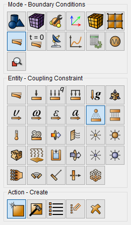
Set the following parameters:
Master and Slave selection;
Master Entity: Vertex;
Entity ID(s): 2 (or select a vertex with the mouse as shown in the figure);
Slave Entity: Vertex;
Entity ID(s): 3;
Choose degrees of freedom: X, Y, Z.
Click Apply.
Add a link to the second pair of vertices in the same way.
Set the following parameters:
Master and Slave selection;
Master entity: Vertex;
Entity ID(s): 4 (or select a vertex with the mouse as shown in the figure);
Slave Entity: Vertex;
Entity ID(s): 5;
Choose degrees of freedom: X, Y, Z.
Click Apply.
3. Set force.
On the command panel, select the boundary conditions module (Mode - Boundary Conditions, Entity — Force, Action - Create).
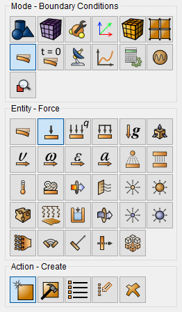
Set the following parameters:
Force Entity List: Node;
Entity ID(s): Select the node in the middle of the horizontal beam with the mouse;
Force: 1000;
Direction: 0 -1 0 (negative direction along the axis y).
Click Apply.
1. On the command bar, select the calculation settings module (Mode — Calculation Settings, Calculation Settings — Static, Static — General).

Set the following calculation parameters:
Dimensions: 3D;
Model: Elasticity.
Click Apply.
Click Start Calculation.
2. In the window that appears, select the directory where the result will be saved and enter the file name.
3. In the case of a successful calculation, the console displays the message: Calculation finished successfully at "date" "time".
1. Open the file with the results. There are three ways to do that.
Click Ctrl+E.
From the main menu, select Calculation. Click Open Results.
Select Results on Command Panel (Mode - Results). Click Open results.

The FidesysViewer window will appear, in which you can view the calculation results.
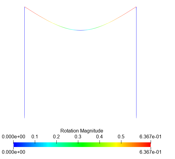
2. Display the deformed view of the model.
Set the focus in the tree of objects to your file in the Tree and display for it Filters - Index - Warp by vector

with the following field values:
Vectors: Displacement;
Scale multiplier: 1.
Set the Rotation Magnitude field to display on the model.

The result is shown in the figure below.
Geometry creating, meshing, setting boundary conditions and materials can be performed using the console interface. Below is a link to the program code that allows you to perform the steps described above manual, you only need to specify the full path and name.