Search the documentation
Enter at least 2 characters
Enter at least 2 characters
 |
CAE Fidesys 9.0 Documentation |
In this problem, the support (point A) of a massless beam is affected by an accelerogram presented as a response spectrum of absolute acceleration.
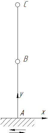
The beam is rigidly fixed at point A. Along the entire beam, linear movement along the Z axis is prohibited. Length AB = BC = 2. At points B, C there is an inertial element with one node of mass 100.
Beam material parameters: Young's modulus E = 2e11; Poisson's ratio ν = 0.3; Density ρ = 1e-07. Relative damping coefficient of 2% on each mode.
To carry out linear spectral analysis, you need to prepare a file in * .csv format with a response spectrum. The file should contain a table where the first column has the frequency (Hz) values, and the subsequent ones - displacements (speed, acceleration). Column names are required:
You can read more about the column names in the Linear Spectral Analysis section.
This table is created as a CSV file and then imported into the Fidesys Viewer (the image shows a sample table in Excel).

Note: Microsoft Excel can open a csv file like this:

i.e. without splitting the file into columns and listing the values of the file lines separated by commas.
To divide the test in rows by the corresponding columns, you need to put a comma in the list separator settings of your operating system.
It should be noted that if the settings are not changed, the file will not load correctly.
1. Create a structure with two beams (AB and BC).
On the command bar, select the module for constructing geometry (Mode — Geometry, Entity— Curve, Action — Create).
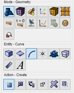
Select Line from the dropdown list.
On the Build Using panel, select Locations.
Next, specify the necessary data to create the first line:
Location: 0 0 0 (separated by a space);
Location: 0 2 0.
Click Apply.
Specify the required data to create the second line:
Location: 0 2 0 (separated by a space);
Location: 0 4 0.
Click Apply.
2. Grow vertices on the resulting beams.
On the command bar, select the module for constructing geometry (Mode — Geometry, Entity — Vertex, Action — Merge).
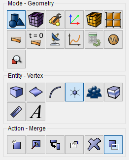
Specify:
Click Apply.
As a result we get a beam structure.

1. On the command bar, select the mesh module (Mode — Mesh, Entity — Curve, Action — Mesh).

Set the following parameters:
Select Curves: all;
Select the mesh creation method: Bias;
Select build options: Auto.
Click Apply Size.
Click Mesh.
1. Create the material.
In the command bar, select the module for specifying material properties (Mode — Material, Entity — Material Management).

In the opened Material Management widget, in the middle column, specify the name of the material material1.
In the properties column, open the Elasticity list and drag the name Isotropic Material to the Material Properties column.
In the Properties column, open the General list and drag the Density name into the Material Properties column.
Fill in the properties as follows:
Young's modulus: 2e+11;
Poisson's ratio: 0.3;
Density: 1e-07.
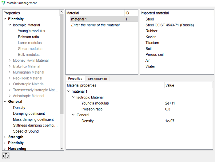
Click Apply.
Close the Materials management window.
2. Create a block type.
On the command bar, select the block management module (Mode — Blocks, Entity — Block, Action — Add).

Set the following parameters:
Block ID: 1;
Entity List: Curve;
Entity ID(s): 1 2.
Click Apply.
To create vertex blocks:
Block ID: 2;
Entity List: Vertex;
Entity ID (s): 4 2.
Click Apply.
To create the second block of vertices, do the same, only put 3 in the ID block, and 4 in the ID of the object.
3. Set the block parameters.
On the command bar, select the block management module (Mode - Blocks, Entity - Block, Action - Block properties/parameters).

Set the following parameters:
Block ID(s): 1;
Category: Beam;
Material: material 1;
Coordinate System: Global Cartesian;
Order: 2.
Click Set Beam Properties.
Specify the following parameters:
CS Rotation Angle: 0;
Calculate relative to: Center of mass;
Select profile: Custom Section;
Y Eccentricity: 0;
Z Eccentricity: 0;
Inertia moment Iy: 0.5e-5;
Inertia moment Iz: 0.5e-5;
Inertia moment Ip: 0;
Inertia moment Iyz: 0;
Inertia moment on torsion It: 0;
Area: 0.00785398;
Max Y coordinate: 0;
Max Z coordinate: 0;
Shear coefficient YY: 1;
Shear coefficient ZZ: 1;
Shear coefficient ZY: 0;
Shear center Y: 0;
Shear center Z: 0;
Warping constant Iω: 0.
Click Apply.
Close the window Set Beam Properties.
Click Apply.
4. Set the block parameters.
On the command bar, select the block management module (Mode - Blocks, Entity - Block, Action - Block properties/parameters).
Set the following parameters:
Block ID(s): 2 3;
Category: Lumped Mass;
Coordinate System: Global Cartesian;
Order: 2.
Set the properties of the point mass, to do this, click on the button
 .
.
Set the following parameters:
Mass: 100;
Inertia moment : 0.
Click Apply.
Close the window Set Lumped Mass Properties.
Click Apply.
1. Fix vertex A along all linear displacement and rotations.
On the command panel, select the boundary conditions module (Mode — Boundary Conditions, Entity — Displacement, Action — Create).

Set the following parameters:
Entity List: Vertex;
Entity ID(s): 1;
Degrees of Freedom: All.
Click Apply.
2. Fix the entire beam in a linear motion along the Z-axis.
Set the following parameters:
Entity List: Curve;
Entity ID(s): All;
Degrees of Freedom: Z-Translation Disp.
Click Apply.
1. et the general settings for modal analysis.
On the command bar, select the calculation settings module (Mode — Calculation Settings, Calculation Settings — Mode Fequency Analysis, Mode Frequency — General).
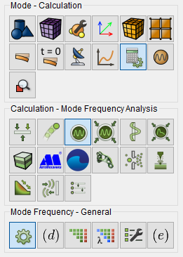
Set the following parameters:
Dimensions: 3D;
Type: Response Spectrum;
Number of Eigenmodes: 2.
Click Apply.
Click Start Calculation.
2. In the window that appears, select the directory where the result will be saved and enter the file name.
3. In the case of a successful calculation, the console displays the message: Calculation finished successfully at "date" "time".
Get results:
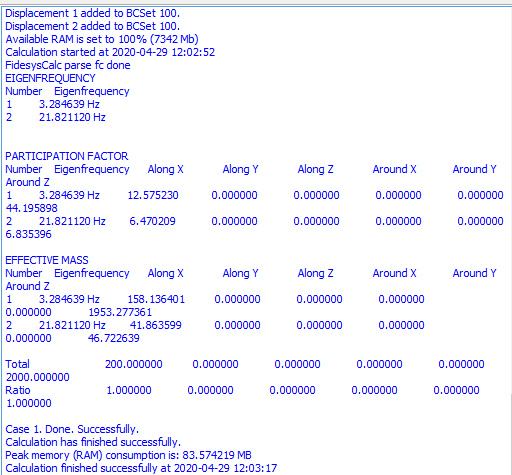
1. Open the file with the results. There are three ways to do that.
Click Ctrl+E.
From the main menu, select Calculation. Click Open Results.
Select Results on Command Panel (Mode - Results). Click Open results.

The Fidesys Viewer window will appear, in which you can view the calculation results.
1. Start Fidesys Viewer with the key combination ctrl + E or in the main menu go to the tab Calculation-Open results in a new window.
In the main menu, go to Filters-Alphabetical-Linear Spectral Analysis.
In the project tree, turn on the visibility of Linear Spectral Analysis and in the Properties tab, set the following parameters:
Check the box opposite the method of combining mods Absolute sum;
Check the box next to the mod combination method Square root of the mod sum;
Check the box next to the method of combining modes Full quadratic combination;
Modal relative damping coefficient Modal damping factor: 0.02;
Specify the path of the CSV file on your computer.
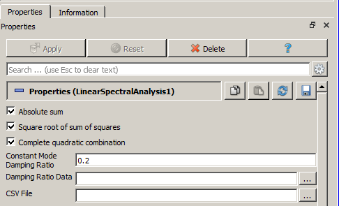
Click Apply.
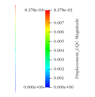
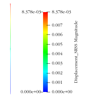
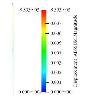
1. Output the results of displacements along the X-axis, obtained by different methods of mod combination.
In the drop-down list of results, select the results Move_AbsSum,Move_PCK,Move_KKSK;
Select X from the drop-down list of coordinate axes.
Geometry creating, meshing, setting boundary conditions and materials can be performed using the console interface. Below is a link to the program code that allows you to perform the steps described above manual, you only need to specify the full path and name.