Search the documentation
Enter at least 2 characters
Enter at least 2 characters
 |
CAE Fidesys 9.0 Documentation |
This finite element is used to create remote boundary conditions. Additionally, it is necessary to create links between the "point" and nodes of other finite elements. This way you can easily create boundary conditions outside of your geometry. As an example, consider a solid body in the form of a cantilever cylindrical beam. A lever is attached to the free edge of the beam, to which forces are applied along the X and Z axes. A sketch of the example is shown in the figure.
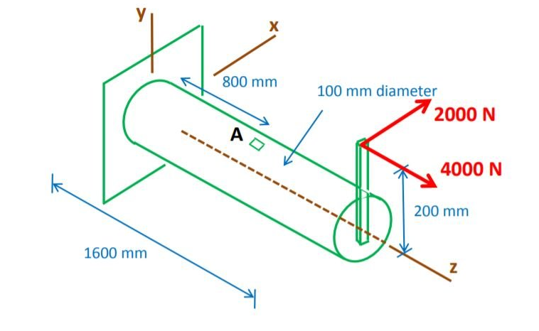
Thus, in order to simulate this task, it is not necessary to draw the entire model completely. It is enough to depict a beam without a lever. Next, you need to create a "point" element at a distance of 200 mm from the center of the free edge of the beam and create a connection between the "point" and the nodes of the free edge. Forces are applied to this element along the X and Z axes. Also, a "point" in combination with connections can be used to specify the movement of aggregates of nodes of the model under study as a rigid whole. For example, we can add a rotating degree of freedom for a solid model.