Search the documentation
Enter at least 2 characters
Enter at least 2 characters
 |
CAE Fidesys 9.0 Documentation |
CAE Fidesys supports point masses (lumped mass elements).
To set point mass properties, go to (Mode – Blocks, Entity – Block, Action - Block properties/parameters).
Category when specifying the element type, the block must have Lumped Mass.

When you select the Lumped Mass category, the Block Properties ID button should appear. In this case, it is possible to create a new prorerties of the lumped mass or select existing IDs.
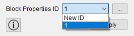
When clicking on the button  a new window opens to set the required parameters. Specify:
Mass;
Inertia moment;
Click Apply.
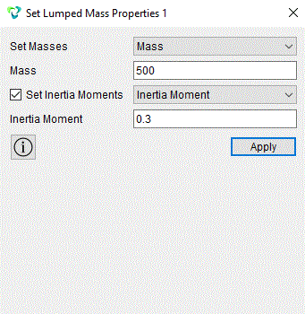
The point mass has dimension 1D, consists of a single point. It is used mainly for the calculation of mobile mechanisms. To solve for mobile mechanisms , the method of substituting masses is used - each the link of the mechanism must be replaced by two concentrated masses.
1. In the first step of point mass modeling, create a vertex for to do this, select (Mode - Geometry, Entity - Vertex, Action - Create). In the pop-up list, select a Location.
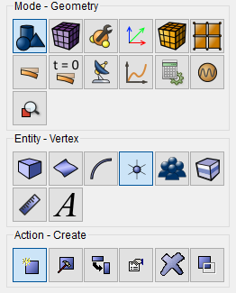
Set the following values:
Location: 0 0 0 (separated by a space).
Click Apply.
This is how the vertex is constructed.
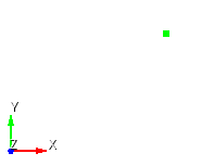
2. Next, create a grid for the constructed vertex, to do this, select (Mode - Mesh, Entity - Vertex, Action - Mesh).
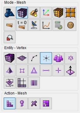
In the pop-up list, select Mesh, left-click with the mouse on the previously constructed vertex, 1 will appear in the vertex ID(s) line.
Click Mesh.
This is how the mesh for the vertex is created.
3. In the next step, select (Mode - Blocks, Entity - Block, Action – Add).

Specify:
Block ID: 1;
Block Name: Point Mass;
Entitiy List: Vertex;
Entity ID(s): left-click on the line object ID(s) and then use the mouse cursor to select a previously constructed vertex.
Click Apply.
This is how the block for the vertex is created.
4. Set the block element type, to do this, select (Mode - Blocks, Entity - Block, Action - Block properties/parameters).
Specify:
Block ID(s): 1 (a point mass will appear in the Block Name line (ID 1));
Category: Lumped Mass.
Click Apply.
As a result , an element called a Lumped Mass was created from a simple vertex.
Next, the point mass needs to be set properties. Click on Set Property point mass.
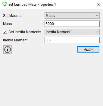
Set the following values:
Weight: 5000;
Moment of inertia: 0.3;
Press Apply. (Note the moment of inertia is the same by default by three components). Thus, a point mass is created from the vertex.
5. Set the necessary boundary conditions for the point mass, namely displacement or anchoring. Select (Mode - Boundary Conditions, Entity - Displacement, Action - Create).

Specify:
Entitiy List: Vertex;
Set the necessary degrees of freedom and magnitudes for your task;
Click Apply.
As a result , boundary conditions were set displacements for the point mass.
Interaction of a point mass and a part (created or imported) in Fidesys, this is done by setting links.
6. Select (Mode - Boundary Conditions, Entity - Coupling Constant, Action - Create).
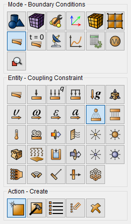
Specify:
Master Entity: You need to select the created or imported one detail. In the List of Entities line, select the entity of this part, to which will be "linked" point mass and set the Entity ID(s);
Slave Entity: In the List of Entities line, select Vertex, set the Entity ID(s). Next, in the pop-up list, select the characteristics by which the bodies will be connected are Degrees of freedom, Temperature, Pore pressure, or the Distance between entities.
Click Apply.
This is how the relationship between the point mass and the part is set.