Search the documentation
Enter at least 2 characters
Enter at least 2 characters
 |
CAE Fidesys 9.0 Documentation |
To calculate structures modeled by rod end elements, it is necessary to set the geometric parameters of the sections of these elements. The geometric parameters of the sections are assigned to the block of elements.
To set beam sections using geometric characteristics or moments of inertia, switch to (Mode – Blocks, Entity – Block, Action – Block Properties/Parameters). The block must be assigned a category Rod.

Rod elements are used in the calculation of statically definable trusses, cable-stayed bridges, etc. in a linear setting or taking into account large deformations.
The use of rods must be carried out on a grid of one element (two nodes), the supported types of analyses are static with and without geometric nonlinearity, without the use of connections and contacts.
The element order for the rods is not applied; by default, the first order is used. The installation of the second and higher order actually means the presence of two rods with a spherical hinge.
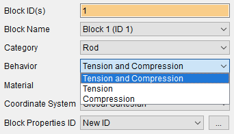
There are possible behaviors for the rod type element:
Tension and Compression;
Tension;
Compression.
When you select the Rod category, you should see a choice of rod behavior and a block property ID button.
When choosing the behavior Tension and Compression, the rod is analogous to the spring element, except that the stiffness of the element is formed from the cross-sectional area and the material used.
When choosing a behavior, Tension allows you to simulate the behavior of cables and other flexible structures that are unable to handle compressive loads.
Such elements are used for calculations of masts, bridges, suspensions, lifting traction and safety devices, devices and equipment with flexible batteries, as well as for calculations of some types of mechanical engineering structures.
When choosing the behavior, Compression allows you to simulate the behavior of supports and other structures that are unable to handle tensile loads.
Such elements are used in the calculations of retaining and safety devices, various types of locking and locking systems, as well as structures in which there is no rigid attachment to the supporting elements.
With the Tension and compression behavior, the element is linear and can be used in modal analysis calculations.
When using this behavior, static calculation can be performed with either geometric non-linearity settings enabled or disabled.
With the behavior of Tension and Compression, the element is nonlinear and may not be used in modal analysis calculations. It automatically replaces the behavior, making the pivot linear. This replacement takes place before the calculation for preloads.
When calculating statics, the geometric non-linearity setting is automatically enabled in the solver settings. When it is turned off, the rod also changes its behavior with the output of a corresponding warning.
With the behavior of Tension and Compression, the element is nonlinear and cannot be used in modal analysis calculations.
When calculating statics, the geometric non-linearity setting is automatically enabled in the solver settings. When it is turned off, the behavior of the rod also changes with the output of the corresponding warning.
In this case, it is possible to create a new section of the beam or select existing IDs.
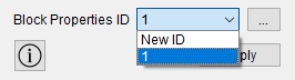
When you click on the button  a new window opens to set the necessary parameters. In the window that
appears, specify:
a new window opens to set the necessary parameters. In the window that
appears, specify:
quality of the cross-section grid;
rotation angle of the coordinate system;
the section profile and its corresponding dimensions.
Click Apply.
CAE Fidesys supports rod sections of the following types:
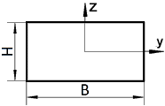 rectangle |
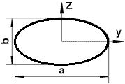 ellipse |
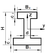 I-beam |
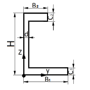 channel |
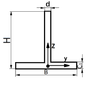 brands |
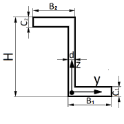 Z-section |
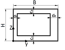 hollow rectangle |
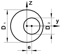 circle with offset hole |
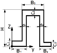 trough profile |
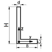 corner |
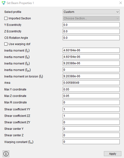 setting the cross section using moments of inertia |
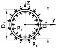 tube |
 View cross
sections of the beam in 3D form are possible in the preprocessor CAE
Fidesys when by clicking the Show 3D view of the beam button.
View cross
sections of the beam in 3D form are possible in the preprocessor CAE
Fidesys when by clicking the Show 3D view of the beam button.
 View cross
sections of the beam in 3D form are possible in the preprocessor CAE
Fidesys when by clicking the Show 3D view of the beam button. To do
this, set the option before starting the calculation Output Fields
- Output results in 3D.
View cross
sections of the beam in 3D form are possible in the preprocessor CAE
Fidesys when by clicking the Show 3D view of the beam button. To do
this, set the option before starting the calculation Output Fields
- Output results in 3D.
For sections defined only with moments of inertia, viewing a 3D view unavailable.
IMPORTANT: This category has one axis, can perceive stretching and compression, and has three degrees of freedom at each node - movement in the directions of the X, Y, and Z axes. As a core element, it has no bending properties. It perceives only the area from the geometry of the section.
IMPORTANT: When calculating farms, it is necessary to calculate statically unchangeable forms.
The static immutability of the trusses of the core system is determined by the order of their formation. The simplest statically immutable hinge system is a triangle having three rods with three hinges. To attach each subsequent hinge in a statically immutable system, two additional rods must be provided. Therefore, in a statically immutable core system with n nodes, there should be:

where n - the number of nodes.
With fewer rods, it would be necessary to create rigid nodes in the farms to ensure static immutability. For example, for a farm consisting of 5 rods (Fig. 1), 4 nodes should be provided.
If the mold contains at least (2n-3) rods, then it is considered immutable. If the number of rods is greater with the same number of nodes, then the farm will be statically indeterminate.
Thus, a four-node shape must have at least 5 rods for its static immutability. For static definiteness, there should be no more than 2n-3 rods. To calculate such a farm, as is known, it is enough to consider three equations of statics.
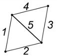
Fig.1 - To verify the geometric immutability and static definiteness of the truss
As it was shown, extra rods (in excess of the amount determined by the specified ratio) give the farm a static indeterminacy. In this case, the static equations are not sufficient to determine the forces in the rods. To calculate them, it is necessary to additionally compile the deformation equations.
IMPORTANT: The rods must be used on a grid of one element (two nodes). The supported types of analyses are static with and without geometric nonlinearity, without the use of connections and contacts.