Search the documentation
Enter at least 2 characters
Enter at least 2 characters
 |
CAE Fidesys 9.0 Documentation |
CAE Fidesys supports springs (spring elements).
1. To set spring properties, go to (Mode – Blocks, Entity - Block, Action - Block properties/parameters).
Category when specifying the element type, the block must have Spring.

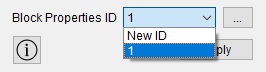
When you select the Spring category, the Block Properties ID button should appear. In this case, it is possible to create new properties or select existing ones ID.
When you click the button  ,
a new window opens to set the necessary parameters. Please indicate:
,
a new window opens to set the necessary parameters. Please indicate:
Spring type;
Values corresponding to the type of spring.
Click Apply.
The spring element has a dimension of 1D, consists of two nodes connected by a segment. It is used to approximate springs when solving deformation problems under the influence of mechanical load.
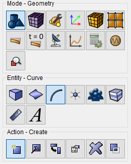
1. In the first step of modeling a spring element, create a line, to do this, select (Mode - Geometry, Entity - Curve , Action – Create).
In the pop-up list, select Line.
Set the following values:
Location and Direction;
Location: 0 0 0 (separated by a space);
Direction: 0 1 0 (separated by a space, one indicates the direction lines along the Y axis);
Length: 2 (line length).
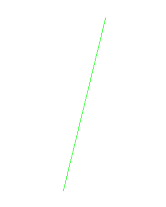
Click Apply. This is how the line is constructed.
2. Next, set the mesh size of the constructed line, to do this, select (Mode - Mesh, Entity - Curve, Action - Mesh).

Set the following parameters:
Select Curves: 1;
Equal;
Interval;
Interval: 1.
Click Apply.
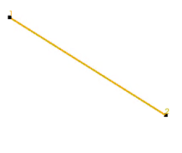
Click Mesh. This is how the meshon the curve is created.
3. In the next step, select (Mode - Blocks, Entity - Block, Action – Add).
Specify:
Block ID: 1;
Block Name: Spring;
Entity List: Curve;
Entity ID(s): left-click on the line entity ID(s) and then use the mouse cursor to select the previously constructed curve.
Click Apply. This is how the first block is created.
4. In the case of spring elements, the block does not need to specify the material. Let's move on to the next step.
Select (Mode – Blocks, Entity - Block, Action - Block properties/parameters).
Specify:
Block ID(s): 1 (Spring (ID 1) will appear in the Block Name line);
Material: choose one of the available (pre-created) materials;
Category: Spring.
Click Apply. As a result, the finite element "Linear spring" was created from the line. Next, it is necessary to assign the mechanical characteristics, which are set in Set Spring Properties.
An important characteristic of the elastic properties of the spring is the stiffness on stretching With, it is determined by the formula:
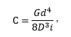
where G is the shear modulus, d is the diameter of the wire, D is the average diameter of the spring, i is the number of turns.
Torsional stiffness is determined by the formula:

where E is Young's modulus of elasticity, d is the diameter of the wire, l is the length of the wire.
To correctly set the torsional stiffness, it is necessary to set the block material.
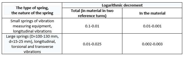
Losses due to vibrations in the spring material (internal friction) and in the support coils (structural friction) differ in nature and magnitude; usually losses caused by the action of dry friction forces between structural elements, more than internal losses, by about one order of magnitude. Quantitative the characteristics are obtained by known methods of recording free damping oscillation or estimation of the width of the resonance curve and reduction to the logarithmic the decrement of oscillations based on the Feucht model. The table below shows some average-approximate experimental data for steel springs.
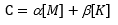
The linear damping coefficient is included in the definition of the damping matrix by Relay. The damping matrix is expressed in terms of a linear combination of matrices mass [M] and stiffness [K], where α is the mass proportionality coefficient (1/s) and β is the stiffness proportionality coefficient (c), in other words, the linear damping coefficient:
After studying the mechanical characteristics, fill in the mechanical characteristics as an example. In the block ID line, enter 1, in the string Stiffness the tensile strength is 1000, the torsional stiffness is 1200. Constant coefficient set the damping and linear damping coefficient to 0.1 and 0.2, respectively. In the Mass line, enter 0.5 and click Apply. As a result, the mechanical characteristics of the spring element are set.
Finite element "Combined spring" (hereinafter referred to as element) includes a system consisting of a parallel connection of a damper, spring and slider and connected in series with the gap. Element sketch presented in the figure.
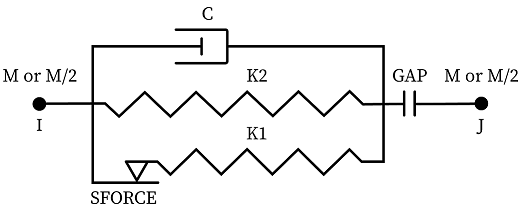
The element is determined by two nodes, the stiffnesses of two springs, the coefficient damping, mass, values of gap and limiting friction-sliding force.
Element settings
Node I;
Evenly on nodes I and J;
Node J.
Stiffness 1 is the stiffness value K1 of the slider, stiffness 2 is the stiffness value K2 of the spring.
If the gap value is positive, then the element works in compression. If - negative, then the element works in tension. If the gap value equals zero - it is excluded from the calculation.
For sliding to occur, the total value of the external forces acting per element, there must be more than the maximum friction-sliding force. Then the total stiffness of the element will be equal to the sum of the stiffnesses of the slider and spring, otherwise, the total stiffness is equal only to the spring stiffness.
The mass (or moment of inertia) can be applied entirely to one node: node I or node J, and be distributed evenly over two nodes.
Note: The unit of damping coefficient is force•time (strength•length•time).
Nonlinear spring - a two-node element with a tabular relationship "Displacement-force" (hereinafter referred to as the table).
The element can have three or six degrees of freedom, depending on the given direction of work. The calculation with six degrees of freedom is not implemented in CAE Fidesys 9.0.
There is no mass or damping. They can be added using a point mass and another type of spring: linear or combined spring.
A nonlinear spring supports all kinds of non-linearities: geometric and physical.
Behavior - the ability to set the behavior of an element under tensile and compressive loads:
Tension and Compression (Sym.) - the element works for stretching and compression, the table will be the same for the two cases;
Tension and Compression (Asym.) - the element works on stretching and compression, there will be two different tables for the two cases;
Tension - the element works only for stretching, for one case - one table;
Compression - the element works only for compression, for one case - one table.
Graphs of the behavior of the spring during conservative unloading are shown in the figure below with the notation of the axes: F (Forse) - force, D (Displacement) - displacement.
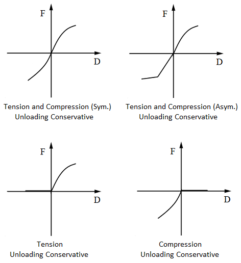
Unloading - controls the behavior of an element during unloading:
Conservative - unloading takes place along the same trajectory as it was in the load;
Non-conservative unloading is not implemented in CAE Fidesys 8.1.
Displacement-force (compression), Displacement-force (stretching) - numerical assignment of tables.