Search the documentation
Enter at least 2 characters
Enter at least 2 characters
 |
CAE Fidesys 9.0 Documentation |
To calculate thin-walled structures modeled by shell finite elements, it is necessary to set geometric parameters of shell sections: thickness and eccentricity. These geometric parameters are assigned to block of elements.
CAE Fidesys supports SHELL/SHELL4/SHELL8/TRISHELL/TRISHELL3/TRISHELL6 shell end elements , spectral shell elements are also supported.
To set shell properties – thickness and eccentricity – go to in (Mode – Blocks, Entity - Block, Action - Block properties/parameters ). The category when specifying the element type to the block must be the Shell.

When you select the Shell category, the Block Properties ID button should appear. In this case, it is possible to create a new section of the shell or select existing IDs.
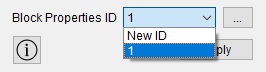
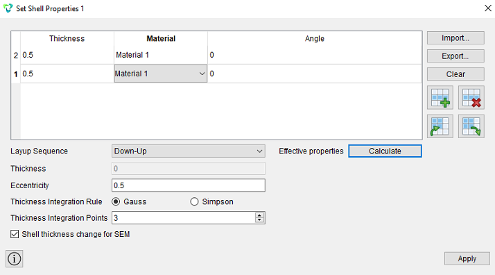
When you click on the "ellipsis" button, a new window opens for setting the necessary parameters. Specify:
The thickness of each shell layer;
Material for each shell layer;
Angle;
Coordinate system;
Eccentricity;
Important: The eccentricity for the shell element varies from 0 to 1 and determines the distance between the shell surface considered in the framework of a geometric or grid model and the median surface shell (in fact, the displacement of the thickness of the median surface relative to the upper surface of the shell in fractions). By default, the eccentricity is set 0.5.
 Viewing a shell section in a 3D view is possible
in the CAE Fidesys preprocessor by clicking the Show 3D View button.
Viewing a shell section in a 3D view is possible
in the CAE Fidesys preprocessor by clicking the Show 3D View button.
 Viewing a section
shells in 3D form are possible in the postprocessor FidesysViewer
when by clicking the 3D view button in the standard line.
Viewing a section
shells in 3D form are possible in the postprocessor FidesysViewer
when by clicking the 3D view button in the standard line.
To specify a multi-layer shell, add another row to the table and fill in as required by the task condition.
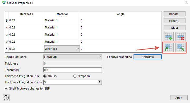
There are also two buttons in this widget for working with tabular data. By clicking the "Copy" button, all cells presented in the table are copied to the clipboard. Next, these cells can be inserted into xls/csv/txt files. By clicking the "Paste" button, cells are inserted from the clipboard instead of existing ones. This way, you can insert a table of shell layer properties from an xls/csv file.
In the case of modeling multilayer laminates with layers lying at an angle to any coordinate system, first a coordinate system is created for a block with shell elements. This coordinate system is projected onto each element and, accordingly, its own coordinate system is formed in each element.
When setting the laminate reinforcement scheme, it is necessary to set the thickness of each layer and the angles of their reinforcement relative to the SC of the block elements. Thus, to analyze the stresses in the layers, it is necessary to derive the stresses in the SC of the layer. In this case, XX stresses can be interpreted as stresses along the fibers, YY stresses across the fibers, and XY as shear stresses in the layer.
To display stresses in the element (and layer) coordinate system, it is necessary to use the "Coordinate systems" filter in the postprocessor: Filters - Alphabetical index - Coordinate systems.
Allows you to visually display the process of inverting layers. Two options can be selected as the sequence of laying the layers:
Down-Up;
Up-Down.
By default, the bottom-up option is selected.
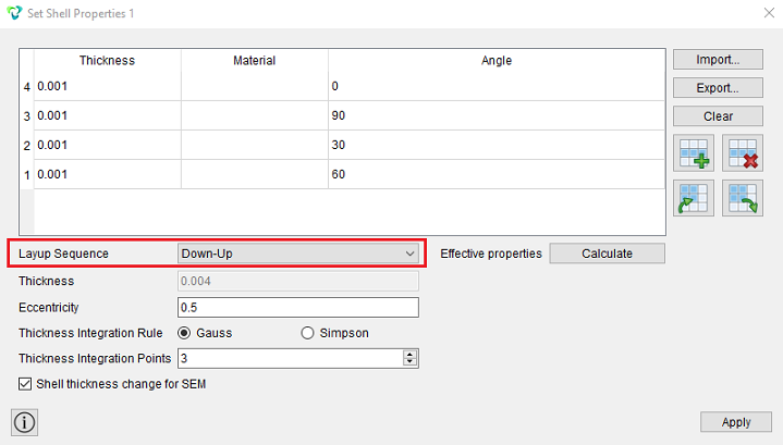
This functionality combines the old "Invert Layers Direction" functionality (version 8.2 and older), as well as a visual representation of the process of changing the laying direction. It only affects the numbering of the layers, the bottom layer of the table will also correspond to the bottom of the shell.
In the widget for specifying shell properties, it is possible to calculate the integral characteristics of multilayer shells.
This function is useful when modeling multilayer shells, when it is necessary to understand what strength and thermoelastic properties the entire multilayer package will have.
For example, if the layer is a multilayer shell:
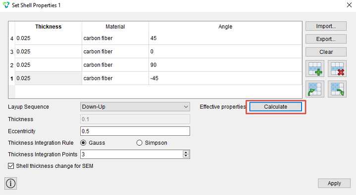
In each layer, the material can be specified by one of the following models: isotropic material, orthotropic material, isotropic transversal. All layers can be oriented at different angles relative to the longitudinal direction (X-axis) of the SC block. Thermoelastic properties are calculated if the thermal expansion coefficients (TEC) are set for the material in each layer.
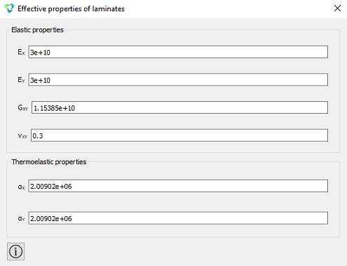
The derived effective properties represent the properties of an orthotropic material, its properties are characterized by four constants of elasticity:
E1 - Modulus of elasticity in the longitudinal direction;
E2 - Modulus of elasticity in the transverse direction;
G12 - The shear modulus;
ν12 - Poisson's ratio.
Thermoelastic properties are characterized by two coefficients of thermal expansion:
α1 - KTR in the longitudinal direction;
α2 - KTR in the transverse direction.
To display stresses and deformations in the multilayer shell layer in FidesysViewer, you need to use the "Coordinate System Conversions" filter.
In the "Properties" of the applied filter, set the following parameters:
Coordinate System: Choose Available;
Choose By Type: Layer CS.
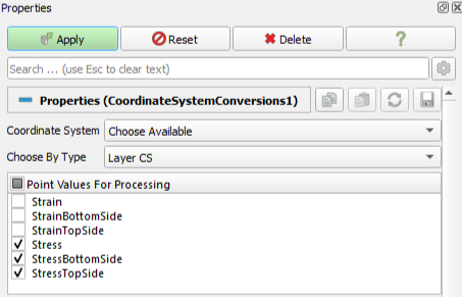
Next, you need to select which layer the voltages will be displayed in.

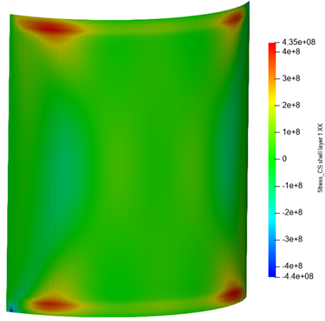
After applying this filter, an array of voltage in this layer will appear in the coordinate system of this layer.
The result of displaying stresses in the middle surface of the shell for the first layer: