Search the documentation
Enter at least 2 characters
Enter at least 2 characters
 |
CAE Fidesys 9.0 Documentation |
In Fidesys, properties of a finite element model such as material, type element, properties of elements (for shells - thickness, for beams - type and cross-sectional size, for springs - stiffness, etc.) can be assigned only a block of elements. Grouping similar elements into blocks represents is a way of creating a new single entity. Preferred is forming blocks using geometric entity definitions: volumes, surfaces, curves or vertices. But blocks can be formed and from mesh entitys. If the block contains geometric entitys, then each of the elements belonging to this geometric entity is automatically assigned to this block. Deleting a geometric entity or repartitioning it to elements automatically changes the set of elements grouped into block. If the block is defined using mesh entitys, then deleting mesh entails complete removal of the corresponding elements from the block.
The following important provisions apply to element blocks:
One block of elements can include many volumes and surfaces and curves.
A volume, surface or curve can only be included in one block elements.
The identification number (ID) of a block of elements can be arbitrary an integer that is defined by the user. Continuous numbering no blocks required.
The block must contain the ID of the geometric model, the name of the material, element type and order. Important: after creating the block, you must set Properties\parameters of the block.
It is recommended to create several blocks if the calculation uses:
several materials (each material must correspond separate block);
several types of geometric entities (the model consists of beams and shells);
several spring stiffnesses;
beams of several types of sections;
or shells of different thicknesses.
For example, if the design contains both solid and shell elements, you need to create a block for each element type. If the design consists of beams with different types of sections, then for each type of section it is necessary create your own block. If the structure consists of different types of elements one category (for example, a mesh of tetrahedrons is built on a three-dimensional model and hexahedrons of the same order), then create several blocks no need.
Let's look at these points in more detail.
1. To create a new block, go to (Mode – Blocks, Entity –Block).

In the panel below, select Action – Add, then select the type of geometric entitys that will be included in the block from list of entities. Then enter the entity ID (or click on those volumes which need to be added to the block).
Click Apply.
ID of geometric entitys that will be included in the block can be found out as follows way:
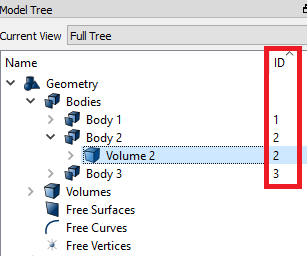
The block ID field must specify a sequence number.
Note: Created block must be displayed in the Model Tree on the left in the section Blocks.
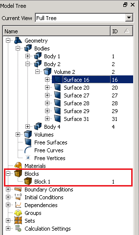
To look through the list of the geometric entities united into the block, enter in Command Line:
List block 1
In the Console, you will see the list of entities united into the block.
Blocks of elements are created using the following commands:
block <block_ID> {vertex | curve | surface | volume} <range> [remove]
block <block_ID> {hex | tet | pyramid | face | tri | edge | node} <range> [remove]
block <block_ID> group <range> [remove]
The first command defines a block based on a list of geometric entitys, and the second uses a list of mesh objects. Since a block may contain only elements of the same type, usually entitys of the same type are grouped into the same block. The third command allows you to combine existing groups of entitys.
Using the remove argument, the specified geometric or mesh entitys are removed from the block.
The commands below are used to assign elements to blocks names and descriptions. Such descriptive characteristics seem more understandable than traditional integer identifiers (IDs). Name and the block description is stored in metadata generated according to DART rules, and are available to the corresponding applications (for example, SIMBA). Assignment Commands names and descriptions look like this:
block<iDs> name "<new_name>"
block<iDs> description "<description>"
This command is also available for nodesets and sidesets.
When assigning a certain material to the elements included in a block,
its properties are associated with the block and exported along with the
mesh.
To assign a pre-created material to a block, you need to use the panel
select commands in (Mode – Blocks, Entity– Block,
Action –Block properties/parameters).

Specify the block ID (or click on the corresponding part of the geometric
models). Next, select the required material from the drop-down list.
Each block must correspond to a certain type of element. To set the element type to the block, select in (Mode – Blocks, Entity –Block, Action – Block properties/parameters).
In the Category field, select the item that corresponds to the entity you added to the block.
Specify the order of the element. In this case, the order can be selected from 1 to 9.
Click Apply.
Important: order 2 corresponds to the selection of a second-order element, where intermediate nodes are added on the faces. Element order 3 onwards means that the calculation will be carried out using the spectral element method the corresponding order (except for the categories of springs and point masses).
To assign a type, use the command:
block <block_ID_range> element <type>
The following categories are available for the corresponding element types:
Point mass: LUMPED MASS.
Spring: SPRING.
Beam: BEAM.
Rod: ROD.
Shell: SHELL.
Plane (2D): PLANE.
Fluid: FLUID.
Solid: SOLID.
If an element type is not assigned to a block, the program selects it by default based on the type of geometry contained in the block. The following rules are used:
Meshes of 8-node hexahedron elements are generated in volumes (HEX8); in the case of using tetrahedral elements, the TETRA4 type is selected.
Meshes of 4-node shells are generated on surfaces elements (SHELL4) having a quadrangle shape in plan; in case When using triangular shaped elements, select the TRISHELL3 type.
Meshes of 2-node linear elements are generated on curves (BEAM2).
Vertices correspond to single-node elements (LUMPED MASS).
Nodes corresponding to the second order of approximation are located in according to the default curved geometry. To change this rules you can use the command:
set node constraint [ON | off | smart]
The off option corresponds to the location of the nodes of the second order without taking into account curved geometry. They occupy the middle positions between the corner nodes of elements: in the middles of straight edges, in the centers flat edges, etc. The smart option ensures that curvature is taken into account only if this does not degrade the quality of the elements.
When exporting an ExodusII file, if the user has not specified any Element Blocks, by default element blocks will be written for any meshed volumes. This default behavior can be changed, to write surface, volume, or no meshes by default. This option can be set using the command
set default block [ON | off | volume | surface]
Default behavior, (ON), is for the blocks to automatically be written based on their owning geometry. When the off setting is used, only the mesh contained in blocks created by the user will be exported. Mesh not in an element block at export time, will not be exported. The export will still succeed and no error will be thrown.
If volume is specified, only elements contained in volumes will have default blocks specified. Similarly, the surface argument indicates that only surfaces containing elements will use default blocks.
When default blocks are used, the IDs for the resulting blocks will be defined as follows based upon the type of geometry:
Volume: The default block ID will be set to the Volume ID;
Surface: The block ID will be set to 0;
Curve: The block ID will be set to.
By default, an element can be included in no more than one block. Using The command below can change this rule. However, it should be noted that since material properties are assigned to a block, creating duplicates of it may result in assigning different materials to the same element. The command to allow the creation of duplicate blocks of elements is as follows view:
set duplicate block elements {on|OFF}
To display blocks of elements in the graphics window, use the following command:
draw block <block_ID_range> [color <color>] [add] [thickness]
For blocks that are of type SHELL and TRISHELL or one of its variants including the [thickness] keyword and parameters will result in the blocks being color-coded by shell thickness with a corresponding color bar. Blocks can be drawn with their specified thickness, so they visually have a thickness. This thickness can also be scaled in the draw command. Arrows defining the shell normal direction will be displayed as well as a legend showing the thickness values.
Block colors can also be changed using the following command:
color block <block_ID_range> {color|default}
All Nodesets, Sidesets and Blocks may be deleted from the model using the following command:
reset genesis
To remove only Blocks, the following may be used:
reset block
To remove a specific block, use:
delete block <block_ID_range>
After a mesh has been defined within a volume, it may be useful to use the existing mesh edges as the basis for an element block. Such an element block might be composed of bars or truss type elements that might propagate through a solid medium such as rebar placed in reinforced concrete. Although the block <ID> edge <range> command could be used for this task, it would prove extremely tedious defining the individual edges to add to the block. To make this process easier, the following command can be used:
rebar start <x> <y> <z> direction <x> <y> <z> [length <value>] block <ID> [element type {bar | bar2 | bar3 | BEAM | beam2 | beam3 }]
The rebar command allows the user to specify a starting location for a set of edges and an initial direction. The program will find the closest existing node in the mesh to start <x> <y> <z> and begin propagating through the mesh in the specified direction <x> <y> <z>, adding edges to the block as it propagates through the mesh. The edge that is attached to the last node and is within a fixed 30 degrees of the specified direction is added to the block. The Propagation of the edges continues until either the optional length value is reached or an edge does not meet the direction criteria. Also required with this command is a block ID. An element type can also be specified.
Similarly, you can use the following command which will use the 30 degree cone described above to gather edges from a surface into a single block using the Cartesian x, y, and/or z vectors.
rebar surface <range> [x] [y] [z] block <ID> [element type {bar | bar2 | bar3 | BEAM | beam2 | beam3 | truss | truss2 | truss3}] [propagate]
Another method for generating rebar blocks include the Diagonal/Orthogonal option. This command can only be used on surfaces that have been meshed with the mapping scheme. This command will create a block of edges from the mapped mesh by starting in one corner and gathering edges orthogonally, or creating new edges diagonally based on the option specified, using the parametric coordinate system dictated by the mapping scheme on the surface. The spacing option dictates how many edges are skipped over before starting the next set of rebar edges.
rebar surface <range> {diagonal | orthogonal} [spacing <int>] [block <ID> [element type {bar | bar2 | bar3 | BEAM | beam2 | beam3 | truss}]
The spacing option determines the number of edges to skip periodically during their sequential search, as shown in Fig. 1 and Fig. 2.
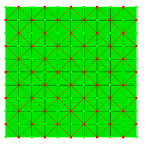
Fig. 1 - Formation of a diagonal block reinforcement with the command rebar surf 1 diagonal spacing 2 block 2
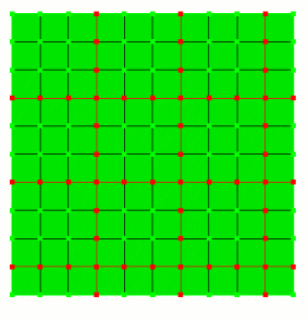
Fig. 2 - Formation of an orthogonal block reinforcement with the command rebar surf 1 orthogonal spacing 3 block 3
A final rebar option allows the user to create or group rebar edges into a specified block using nodes. Edges are created, or gathered, using the ordered list of nodes specified in the command.
rebar node <range> [target block <ID>] [element type {bar | bar2 | bar3 | BEAM | beam2 | beam3 | truss}]
In Fig. Figure 3 shows an example of the formation of such a block using input list of nodes.
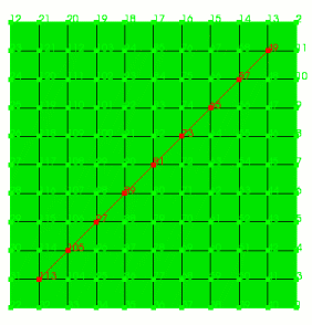
Fig. 3 - Formation of the reinforcement block determined set of nodes (rebar node 113 105 97 89 81 73 65 57 49 target block 1)
A related command for creating curve geometry directly from mesh edges is the Create Curve from Mesh command. See Curve creation for more details.
The related command is а Creation Curve on the Mesh.
The command described below allows you to create special blocks of linear elements that can be used as part of the body's boundary. Elements are formed without creating a corresponding geometric entity:
block <ID> joint {vertex <ID> | node <ID>} spider {surface | curve | vertex | face | tri | node} <range> [preview] [element type {bar | bar2 | bar3 | BEAM | beam2 | beam3 | truss | truss2 | truss3}]
Option joint {vertex <ID> | node <ID>} defines the initial position from which the formation of linear elements begins, and the spider argument with additional parameters (surface, curve, ...) and geometric or mesh identifiers entitys (<range>) - final position. Formed elements can be used to model connections under confinement conditions contact or other boundary conditions. In Fig. 4 shows an example of creating "spider-web" block of beam elements that connect the node, lying on the axis of the cylinder, with each node on its circumference. For this purpose it is used a series of commands like:
block 10 joint node 1 spider node 2
The preview option can be used to display the created block of elements before the direct execution of the command.

Fig. 4 - "Cobweb" beam block elements