Search the documentation
Enter at least 2 characters
Enter at least 2 characters
 |
CAE Fidesys 9.0 Documentation |
The finite element model data is stored in the Fidesys database and transmitted from session to session in binary format. This data includes grid parameters, element properties, information about the problem being solved, and analysis results. When defining properties, elements are grouped into blocks; a block combines elements of the same type from the same material. When defining boundary conditions and loads, node sets and side sets are used. Due to the separation of mesh parameters, element properties, as well as sets of nodes and sides, it is possible to use the same mesh once generated with elements of different types, with different material properties and for different tasks.
A block of elements (or simply a block) is a logical group of elements with the same geometry and number of nodes. The block is accessed using a user-defined identifier (ID). Typically, a block of elements is assigned certain material properties, category and order of the element. A detailed description of working with blocks is given in the section Setting blocks of elements.
Nodesets are a logical grouping of nodes accessed through a user-specified Nodeset ID. Nodesets provide a means to reference a group of nodes with a single ID. They are typically used to specify load or boundary conditions on portions of the CAE Fidesys model or to identify a group of nodes for a special output request in the finite element analysis code.
Sidesets are another mechanism by which constraints may be applied to the model. Sidesets represent a grouping of element sides and are also referenced using an integer Sideset ID. They are typically used in situations where a constraint must be associated with element sides to satisfactorily represent the physics (for example, a contact surface or a pressure.
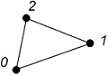
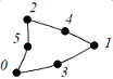
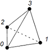
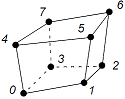
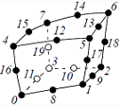
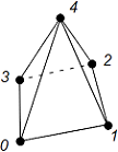
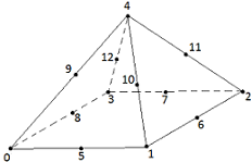
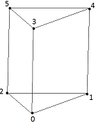
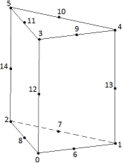
The basic elements used to discretize geometry were described in the mesh generation chapter. Within each basic element type, several specific element types are available. These specific element types vary by the number of nodes used to define the element, and result in different orders of accuracy of the element. The element types available for each basic element type defined in CAE Fidesys are summarized in the following table. For a description of the node and side numbering conventions for each specific element type, see the Appendix. Element types can be set for individual Element Blocks, either before or after meshing has been performed. Higher-order nodes are created only when the mesh is being exported to the Exodus II file, and persist in the CAE Fidesys database after file export.
Table 1 - Finite elements used in Fidesys
Finite element |
Order |
Type |
View |
Beam |
I |
BEAM2 |
2 nodes
|
II |
BEAM3 |
3 nodes
|
|
Triangle(2D) |
I |
TRI3 |
3 nodes (plane)
|
II |
TRI6 |
6 nodes (plane)
|
|
Quadrangle (2D) |
I |
QUAD4 |
4 nodes (plane)
|
II |
QUAD8 |
8 nodes (plane)
|
|
Shell |
I |
TRISHELL3 |
triangle element (3 nodes)
|
II |
TRISHELL6 |
triangle element (6 nodes)
|
|
I |
SHELL4 |
quadrangle element (4 nodes
|
|
II |
SHELL8 |
quadrangle element (8 nodes)
|
|
Tetraherdon |
I |
TETRA4 |
4 nodes
|
II |
TETRA10 |
10 nodes
|
|
Hexahedron |
I |
HEX8 |
8 nodes
|
II |
HEX20 |
20 nodes
|
|
Pyramid |
I |
PYRAMID5 |
5 nodes
|
II |
PYRAMID13 |
13 nodes
|
|
Wedge |
I |
WEDGE6 |
6 nodes
|
II |
WEDGE15 |
15 nodes
|
|
Rod |
I | ROD |
2 nodes
|
Spring |
I | SPRING |
2 nodes
|
Point mass |
I | LUMPMASS |
1 node
|
Point |
I | POINT |
1 node
|