Search the documentation
Enter at least 2 characters
Enter at least 2 characters
 |
CAE Fidesys 9.0 Documentation |
The geometric model of the problem and the mesh are shown in the figure.
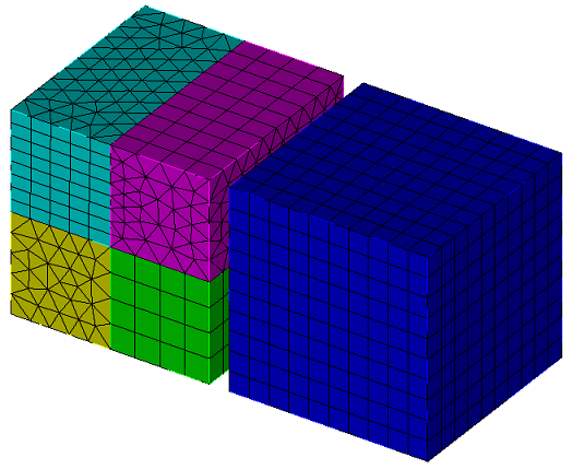
The size of the cubes is 10 m x 10 m x 10 m. The first cube is divided into 4 parts, each of which has its own type of elements. The upper and lower edges are attached pressure: uniform compression.
1. Create the first brick.
On the command bar, select the module for constructing volume geometry (Mode - Geometry, Entity - Volume, Action - Create).

Select from the entire list of geometric primitives Brick.
Set the following parameters:
X (width): 10.
Click Apply.
2. Cut the brick into 4 parts.
On the command bar, select the module for constructing volume geometry (Mode - Geometry, Entity - Volume, Action - Webcut).
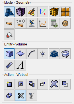
Select from the entire list of possible types of sections Coordinate Plane.
Set the following parameters:
Volume ID(s): 1;
Cut plane: YZ;
Offset Value: 0.
Click Apply.
Do the same but in the ZX plane.
Volume ID(s): all;
Cut plane: ZX;
Offset Value: 0.
Click Apply.
3. The resulting brick are fused together.
On the command bar, select the module for constructing volume geometry (Mode - Geometry, Entity - Volume, Action — Imprint and Merge).
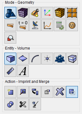
From the drop-down list, select Imprint/Merge Volumes.
Set the following parameters:
Volume ID(s): all.
Click Apply.
4. Create a second brick.
On the command bar, select the module for constructing volume geometry (Mode - Geometry, Entity - Volume, Action - Create).
Select from the entire list of geometric primitives Brick.
Set the following parameters:
X (width): 10.
Click Apply.
5. Move the second brick.
On the command bar, select the module for constructing volume geometry (Mode - Geometry, Entity - Volume, Action - Transform).
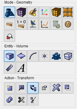
Select from the entire list of possible types of transformations Move.
Set the following parameters:
Volume ID(s): 5;
Include Merged;
Select Method: Distance;
X Distance: 11.
Click Apply.
1. On the command bar, select the volume mesh module (Mode - Mesh, Entity - Volume, Action - Mesh).
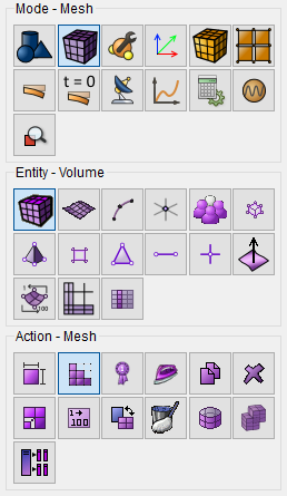
Specify the following parameters:
Select the mesh construction scheme: Polyhedron;
Select Volumes: 1 5.
Click Apply Scheme.
Click Mesh.
2. On the command bar, select the volume mesh module (Mode - Mesh,
Entity - Volume, Action - Mesh).
Specify the following parameters:
Select the mesh construction scheme: Tetmesh;
Select Volumes: 2.
Click Apply Scheme.
Click Mesh.
3. On the command bar, select the volume mesh module (Mode - Mesh,
Entity - Volume, Action - Intervals).
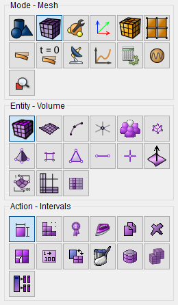
Select the mesh layout: Automatic Sizing;
Select Volumes: 4.
Click Apply Size.
Click Mesh.
4. On the command bar, select the surface mesh module (Mode - Mesh,
Entity - Surface, Action — Mesh).
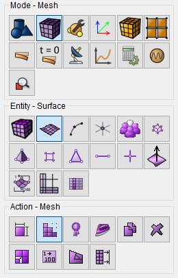
Specify the degree of grinding of the mesh:
Select the mesh construction scheme: Polyhedron;
Select Surfaces: 11 23.
Click Apply Scheme.
Click Mesh.
5. On the command bar, select the volume mesh module (Mode - Mesh,
Entity - Volume, Action - Mesh).
Specify the degree of grinding of the mesh:
Select the mesh construction scheme: Tetmesh;
Select Volumes: 3.
Click Apply Scheme.
Click Mesh.
1. Create the material.
In the command bar, select the module for specifying material properties (Mode — Material, Entity - Materials Management). Enter a name of the LinearMat material.

Drag the Isotropic Material label from the left column to the Properties column of the material. Set the following parameters:
Young's modulus: 2e+11;
Poisson ratio: 0.3.
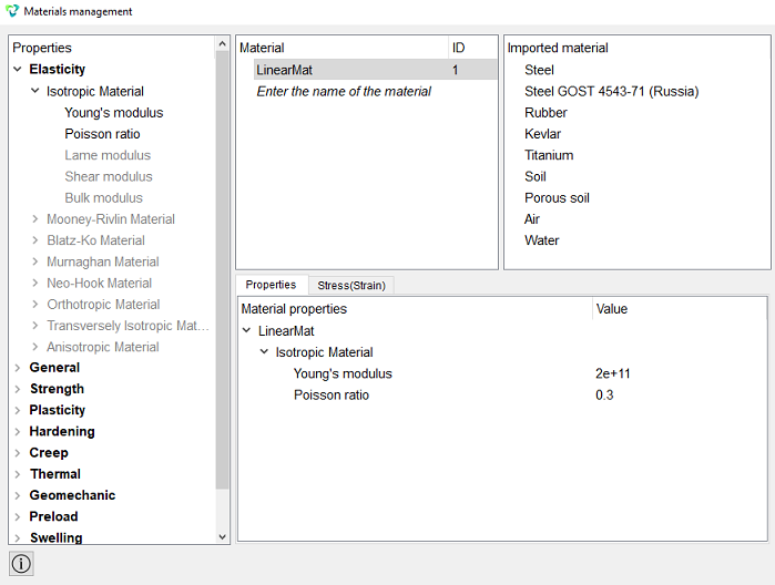
Click Apply.
Close the Materials management window.
2. Create the first block.
On the command bar, select the block management module (Mode- Blocks, Entity - Block, Action — Add).

Set the following parameters:
Block ID: 1;
Entity List: Volume;
Entity ID(s): 1.
Click Apply.
3. Create a second block.
On the command bar, select the block management module (Mode- Blocks, Entity - Block, Action — Add).
Set the following parameters:
Block ID: 2;
Entity List: Volume;
Entity ID(s): 2.
Click Apply.
4. Create a third block.
On the command bar, select the block management module (Mode- Blocks, Entity - Block, Action — Add).
Set the following parameters:
Block ID: 3;
Entity List: Volume;
Entity ID(s): 3.
Click Apply.
5. Create a fourth block.
On the command bar, select the block management module (Mode- Blocks, Entity - Block, Action — Add).
Set the following parameters:
Block ID: 4;
Entity List: Volume;
Entity ID(s): 4.
Click Apply.
6. Create a fifth block.
On the command bar, select the block management module (Mode- Blocks, Entity - Block, Action — Add).
Set the following parameters:
Block ID: 5;
Entity List: Volume;
Entity ID(s): 5.
Click Apply.
7. Assign the material to the blocks.
On the command bar, select the block management module (Mode- Blocks, Entity - Block, Action — Block properties/parameters).

Set the following parameters:
Block ID(s): all;
Category: Solid;
Material: LinearMat;
Order: 2.
Click Apply.
8. Select the blocks that will participate in the calculation.
On the command bar, select the block management module (Mode- Blocks, Entity - Blocks to calculate).
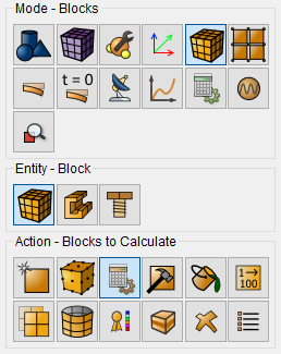
Set the following parameters:
Blocks to calculate: 5;
Action: Off.
Click Apply.
1. Fix the left face in the X direction.
On the command panel, select the boundary conditions module (Mode - Boundary Conditions, Entity - Displacement, Action — Create).

Set the following parameters:
Entity List: Surface;
Entity ID(s): 36 28 (separated by spaces);
Degrees of Freedom: X.
Click Apply.
2. Fix the bottom edge in the Y direction.
On the command panel, select the boundary conditions module (Mode - Boundary Conditions, Entity - Displacement, Action — Create).
Set the following parameters:
Entity List: Surface;
Entity ID(s): 16 9 (separated by spaces);
Degrees of Freedom: Y.
Click Apply.
3. Fix the back face in the Z direction.
On the command panel, select the boundary conditions module (Mode - Boundary Conditions, Entity - Displacement, Action — Create).
Set the following parameters:
Entity List: Surface;
Entity ID(s): 29 21 23 35 (separated by spaces);
Degrees of Freedom: Z.
Click Apply.
4. Apply pressure to the upper face.
On the command panel, select the boundary conditions module (Mode - Boundary Conditions, Entity - Pressure, Action - Create).
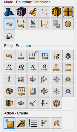
Set the following parameters:
Entity List: Surface;
Entity ID(s): 13 11 (separated by spaces);
Value: 1e6.
Click Apply.
1. Specify the type of task that you want to solve.
On the command bar, select the calculation settings module (Mode - Calculation Settings, Calculation settings — Static, Static — General).

Set the following settings:
Dimensions: 3D;
Model: Elasticity.
Click Apply.
2. Set the solver parameters.
On the command bar, select the calculation settings module (Mode - Calculation Settings, Calculation Settings — Static, Static - Solver).
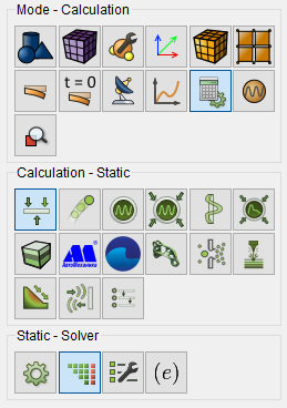
Set the following settings:
Method: Iterative;
Use Uzawa Iteration: No;
Preconditioner: Choose Automatically.
Click Apply.
Click Start Calculation.
2. In the window that opens, select the directory where the result will
be saved, and enter the file name.
3. In the case of a successful calculation, the console displays the message:
Calculation finished successfully at "date" "time",
and there will also be the required values of eigenvalues and frequencies
are derived.
1. Open the file with the results. There are three ways to do that.
Click Ctrl+E.
From the main menu, select Calculation. Click Open Results.
Select Results on Command Panel (Mode - Results). Click Open results.

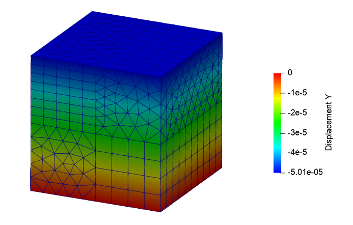
2. Display the uy component of the displacement fields.
In the FidesysViewer window that appears, set the following parameters on the toolbar:
Display field: Displacement;
Display component: Y;
Display type: Surface With Edges.
The model displays a field for the distribution of displacements along the Y axis.
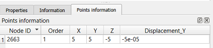
Select a point (5, 5, -5) on the geometric model.
To quickly view the information in the selected point, click on the main Point Information panel.

The window that appears displays the components of the movements at the selected point.
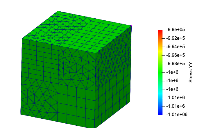
3. Display the component σyy of the stress field.
On the toolbar, set the following parameters:
Display Field: Stress;
Display component: YY;
Display type: Surface With Edges.
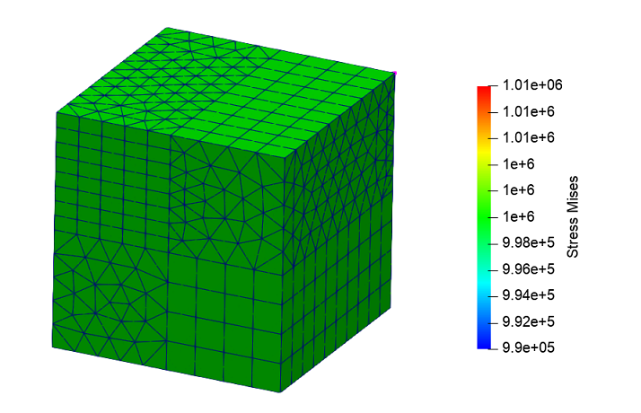
4. Display the component σMises of the stress field.
On the toolbar, set the following parameters:
Display Field: Stress;
Display component: Mises
Display type: Surface With Edges.
Geometry creating, meshing, setting boundary conditions and materials can be performed using the console interface. Below is a link to the program code that allows you to perform the steps described above manual, you only need to specify the full path and name.