Search the documentation
Enter at least 2 characters
Enter at least 2 characters
 |
CAE Fidesys 9.0 Documentation |
Heat source can be applied as a load on most types geometric and mesh entity.
To create or change the boundary conditions of a heat source, you should:
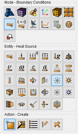
Select Mode - Boundary Conditions on the Command Bar, Entity - Heat Source.
Depending on the situation, select Action - Create or Action - Modify.
Using GUI elements, set identifier (ID) or name of a set of boundary conditions, indicate entity, which restrictions are imposed, and enter the heat source value.
Click Apply.
The corresponding commands for these interactive operations are:
create heatsourcepoint [ID] [name <'name'>] [{add | on} {nodeset | volume | surface | curve | vertex | node} <entity_list>] [value <val>]
modify heatsourcepoint {ID_list|'name'|all} [name <'name'>] [{add | remove} {nodeset | volume | surface | curve | vertex | node} <entity_list>] [value <val>]
For example, to set the heat source for volume 2 to 1000, you can specify on the command line:
create heatsourcepoint on volume 2 value 1000
The heat source can be applied to:
volumes;
surfaces;
curves;
vertex;
node;
nodeset.
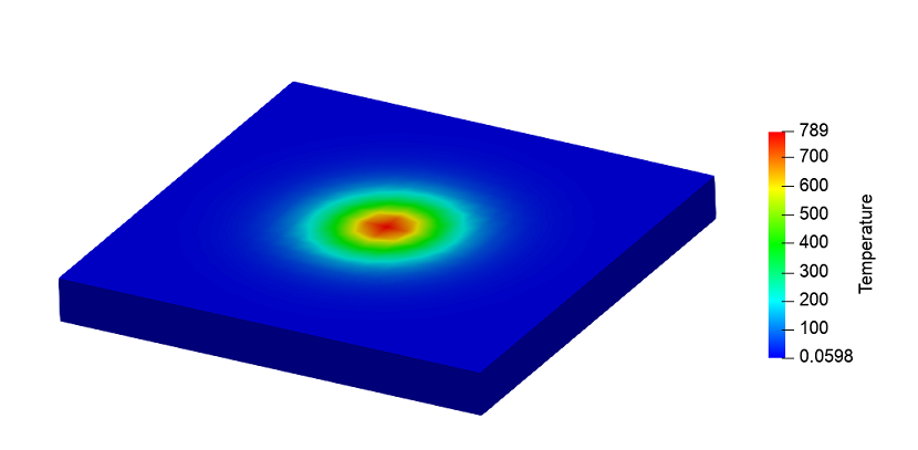
A parallelepiped made of carbon steel with dimensions of 0.1*0.1*0.01 m is specified. A heat source is applied to the upper face according to the formula:

Thermal fields after 10 seconds of heating: