Search the documentation
Enter at least 2 characters
Enter at least 2 characters
 |
CAE Fidesys 9.0 Documentation |
To construct a finite element mesh from hexahedrons, many volumetric geometric models require preliminary division into parts (decomposition). The most commonly used algorithm for dividing into hexahedrons is Sweep. It is the process of creating a hexahedral mesh by advancing a surface mesh of quadrilaterals from a starting surface (source) to a topologically similar destination surface (target) along a third surface connecting them. The surface mesh on the initial surface is created using a suitable partitioning scheme and can be either regular or irregular. The most suitable for running the Sweep algorithm is the surface partitioning scheme Unstructured mesh. As a rule, the geometric models being analyzed are not suitable for automatic sweep, so dividing them into parts suitable for this purpose is an important part of the mesh construction process. Decomposition typically involves a series of cuts, Boolean operations, and virtual geometry operations that break the original model into components suitable for sweep. Such activities take up most of the total time in creating a finite element model. The purpose of this tutorial is to:
To teach the user to recognize volumes suitable for sweep.
To provide an understanding of how to divide the model into the appropriate parts.
To instill skills for making the necessary cuts in the model, as well as to familiarize with other decomposition methods.
To help avoid problems inherent in decomposition and sweep.
Of all the algorithms, or hexahedral partitioning schemes, provided in Fidesys, Sweep can be considered the most reliable way to create high-quality elements. Although dividing the model into parts suitable for sweep can be time-consuming, in some cases it is the only way to build a hexahedral volumetric mesh.
Topological structures suitable for constructing a mesh using the Sweep scheme, can be divided into three main types depending on the number of initial and final sweep surfaces.
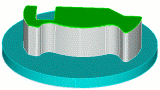
One source - one target: Volume with one initial and one final surfaces, Fig. 1:
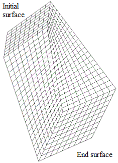
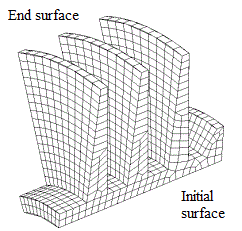
Fig. 1 - Examples of topological structures: one source - one target.
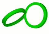
Many sources - one target: Volume with many initial surfaces and one final, Fig. 2:
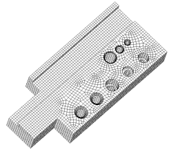
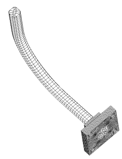
Fig. 2 - Examples of topological structures: many sources - one target.
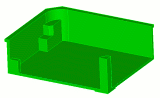
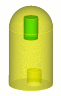
Many sources - many targets: Volume with many initial and final surfaces, Fig. 3:
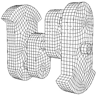
Figure 3 - Examples of topological structures: many sources - many targets.
The surface mesh can be sweep through a volume obtained by rotation or plane-parallel translation. However, if the body shape changes abruptly, the quality of the volume mesh may be low.
A volume with multiple end surfaces and one initial surface can in some cases be inverted and treated as a volume of the second type (many sources - one target). Otherwise, it is treated as a volume of the third type (many sources - many targets).
Projection introduces new topological entity to surfaces. Therefore, volumes that were initially suitable for sweep may become unsuitable after projection and merging of adjacent surfaces.
The sweep for topological structures of the many sources - many targets type is in the stage of unfinished development and has a number of limitations. Therefore, it is better to divide the volume into parts related to the second or first types.
Fidesys does not always automatically recognize a volume as suitable for sweeping, even if it is. Sometimes you will have to explicitly set the start and end surfaces.
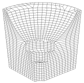
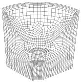
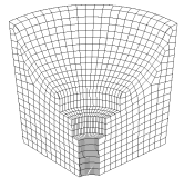
In addition to the different topological types, volumes are classified and with respect to the direction of sweep. The following directions (or methods) are used: "top-down", "inside-out", and "in a circle" (rotation). When starting to decompose the model, make sure that you have considered all possible ways of sweep. The chosen direction must be compatible with the adjacent volumes. For compatibility, overlapping surfaces must be of the same type: either a connecting surface or a surface broken into elements according to the Unstructured Mesh scheme. The volume shown in Table 1 is broken up in three different ways, each with a different sweep direction. Note the differences in the size and orientation of the elements. As an exercise, try breaking up this model using other sweep directions.
Table 1. - Examples of the influence of different directions of sweeping on the appearance of a volumetric finite element mesh.
 |
 |
 |
Top to Bottom |
Inside to Out |
Circle |
Many Sources - One Target |
Many Sources - One Target |
One Source - One Target |
Determining whether a volume is suitable for sweeping is a difficult task in itself, but coming up with effective strategies for performing cuts, boolean operations, and constructing virtual polysurfaces to make the volume suitable is an even more difficult problem. Below are some general principles that it is advisable to follow when decomposing a model.
Select the direction of the sweep.
Use the least number of cuts possible.
If the start and end surfaces are not selected automatically by the program, specify them yourself.
If any of the volumes are not broken into elements or the mesh has an undesirable appearance, try changing the order of partitioning of the volumes. This will redefine the partition intervals.
The reset volume command will remove all previously defined partition schemes and intervals.
If changing the split order or clearing volumes does not produce the desired result and you still receive the error message: Matching Intervals Failed, set intervals explicitly for some or all curves.
Make additional cuts if necessary.
Check for any small surfaces or curves that may have been introduced during the decomposition process and remove them by smoothing, squeezing, or combining them into a composite geometry.
If you want to force the mesh into a specific configuration, such as conforming to the Regular Mesh meshing scheme, modify the vertices that make up the surface as appropriate.
Use virtual geometry operations that do not affect the original geometry.
Use composite surfaces within virtual geometry to overcome meshing limitations (without affecting the original geometry).
Continuously save your work. For a complex model, the meshing process may be iterative. You may have to start over several times until you find an acceptable solution.
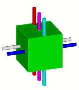
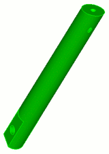
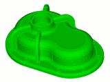
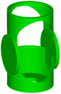
Table 2 presents a set of examples of decomposition of models of varying
complexity. Each example corresponds to a file with geometry data, located in
the subfolder
.../help/step_by_step_tutorials/decomposition, created during installation
of the program (optional).
Table 2. - Examples of decomposition of models of varying complexity.
Example |
Model View |
Data File |
Beginner |
||
|
example01.sat |
|
|
example02.sat |
|
|
example03.sat |
|
|
example04.sat |
|
|
example05.sat |
|
Advanced level |
||
|
example06.sat |
|
|
example07.sat |
|
Example 8: Sweeping through volumes with sharp corners and narrow surfaces |
|
example08.sat |