Search the documentation
Enter at least 2 characters
Enter at least 2 characters
 |
CAE Fidesys 9.0 Documentation |
Below is another example of using different directions of sweeping for the same model. The model is a cube pierced by several cylindrical rods. The rods do not intersect each other.
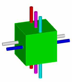
Fig. 1 - Geometric model.
Table 1. - Types of sections for creating geometry suitable for constructing a mesh by the sweeping method
Section view |
Commands |
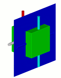 |
FIDESYS> webcut volume all with plane yplane offset 20 |
 |
FIDESYS>
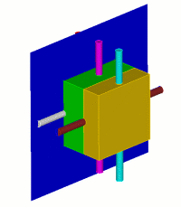
webcut volume all with plane yplane offset -20 |
All volumes obtained by cutting the original model are now suitable for sweeping in the one source - one target manner. However, for the cube components, the initial and final surfaces must be specified explicitly:
Table 2. - Specifying the mesh construction scheme.
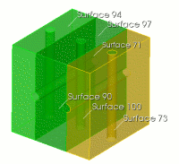 |
FIDESYS>volume 8 scheme Sweep source surface 94 target surface 90 rotate off FIDESYS>volume 10 scheme sweep source surface 71 target surface 73 rotate off FIDESYS>volume 12 scheme Sweep source surface 97 target surface 100 rotate off FIDESYS>volume all size 2 FIDESYS>mesh volume all |
For the model under consideration, different directions of sweeping are possible, since the superimposed surfaces are simultaneously connecting surfaces. The constructed mesh consists of elements of size 2, Fig.
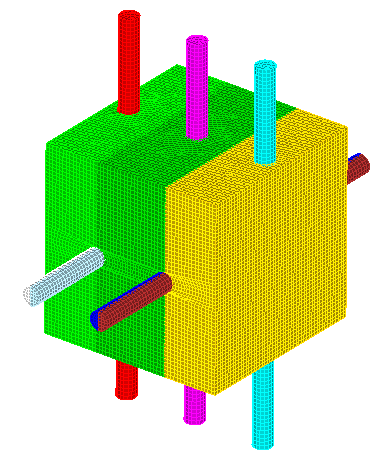
Fig. 2 - Resulting mesh