Search the documentation
Enter at least 2 characters
Enter at least 2 characters
 |
CAE Fidesys 9.0 Documentation |
Power Tools geometry operations are activated by clicking on the Model Tree icon located at the top left of the Power Tools Panel:
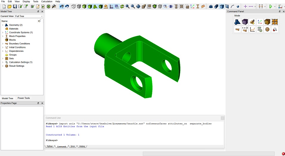
Fig. 7 - Activating power tools.
It is possible to perform a number of operations related to the analysis and correction of geometry. Some geometric models imported from other solid modeling programs may contain inconsistencies or small gaps that do not allow the construction of a finite element mesh. Such problems are caused by differences in acceptable modeling errors, data loss during file conversion, and internal limitations of generating systems. On the other hand, the geometry may not contain any inconsistencies, but it is unsuitable for meshing due to topological features such as small angles, overlapping parts, or the presence of parts smaller than the intended meshing interval. Using the geometry analysis tools, you can check and get a list of existing problems. To see the list of analysis options, click on the Diagnose Geometry icon, (one to the right of the Tree icon), and then click the Options button. The parameters to be checked (analyzed) include: small features, small angles, overlaps, poor outlines (poorly defined surfaces).
Most of the problems found can be fixed using the Power Tools menu. This menu (see below) includes tools that perform the following operations: Split Surface, Healing, Tweaking Geometry of a surface or curve, Merging Geometry, Removing Geometric Features, Composite Geometry (curves or surfaces), Collapse Geometry (angles, curves, surfaces). Some of these tools are demonstrated in this tutorial.
When you click on the Diagnose Geometry icon, all (all volumes) appears by default in the Body ID input window, and 1 appears in the Small Curve Threshold input window. If necessary, this data can be changed.
Click Analyze:
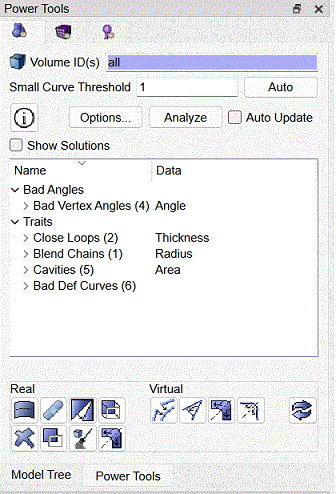
Fig. 8 - Power Tools Panel.
The list of existing problems displays information about four geometry problems that were detected: low-angle curves, mixed surfaces, closely spaced curves, and poorly defined geometry. Clicking on a specific entity specified in this list (a surface, curve or vertex) causes it to be highlighted in a contrasting (orange) color on the model in the graphics window.
Select the vertex 45 from the data on curves with small angles (Vertex 45).
Note the corresponding selection of this vertex in the graphics window.
Right-click on the vertex pointer 45 in the list, and on the additional panel that appears select the option Zoom in.
The image of the model is shown in Fig. 9:
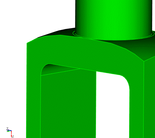
Fig. 9 - Image of the model after zooming in.
Right-clicking the vertex pointer again 45 and selecting the Reset Zoom option on the additional panel returns the previous view.
The above operations are described in more detail in the section Geometry Power Tools.
You can experiment with other options in the additional panel that appears when you click the right mouse button, in particular, with such as:
Zoom To.
Locate.
Draw (in the previous version of the program Drawing).
Draw With Neighbors (conjugate curves and surfaces).
Reset Graphics.
If you need to clear the graphic window, click the icon  on
the Toolbar.
on
the Toolbar.

