Search the documentation
Enter at least 2 characters
Enter at least 2 characters
 |
CAE Fidesys 9.0 Documentation |
The geometry power tools, shown in Fig. 1. are located on the Tree View window under the blue geometry tab. The Geometry Power Tool provides several diagnostic tests to identify and repair problems in your CAD model prior to meshing including.
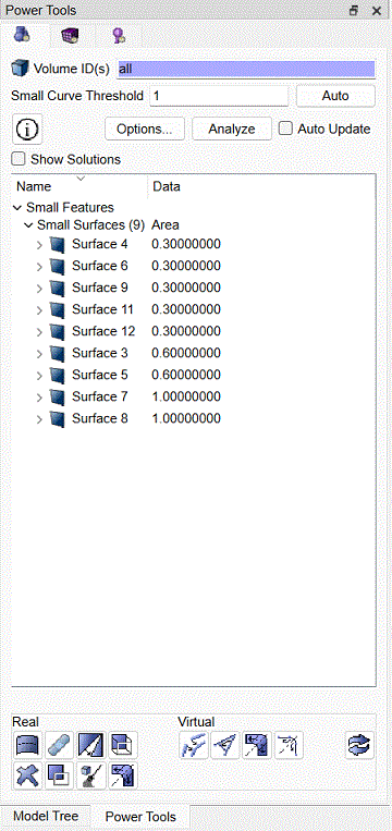
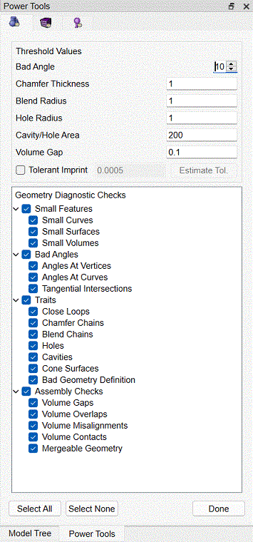
Fig. 1. Geometry Power Tools
Diagnostic tests include:
This tool analyzes geometry for various characteristics that may affect meshing outcomes and aid in simplification and defeaturing. It also contains a powerful toolkit of geometry modification methods to fix these problems. Many of the common geometry clean-up tools are available from this tool without the need to search through the command panels for relevant operations.
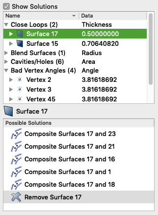
The geometry power tool includes a window that lists results from geometry analysis in a tree format. In addition, a solution window can be displayed that will display specific suggested geometry solutions for the currently selected entity.
The following is a suggested workflow for using the geometry power tool:
 |
 |
|
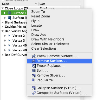
Fig. 3. Geometry entity context menu in power tool |
Fig. 4. Entitiy-specific solutions displayed in geometry power tool |
The geometry power tools contain an array of tests that can be run on geometry to diagnose potential problems for mesh generation. To display a list of tests, click on the Show Options check box. By default all tests are selected and run on geometry. Some tests may not apply to specific geometry, or may only need to be run once per geometry (i.e. bad geometry definition test). Clicking on the box by each test will deselect it. The geometry analysis inputs and tests are summarized below:
Small Features.
Small features may be necessary and desirable in a model, but many times they are the result of poor geometry construction, or they may just not be important to the analysis. The small features tests look for small curves, small surfaces, and small volumes. These tests rely on the user-defined small curve threshold value defined at the top of the Geometry poert tool.
Bad Angles
Small geometric angles at vertices and curves can sometimes over-constrain the resulting mesh resulting in poor element quality. These tests are controlled by the Bad Angle threshold value defined at the top of the Geometry power tool Options panel.
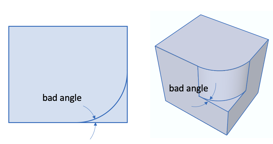
Fig. 5. Bad Angle at Vertex Example
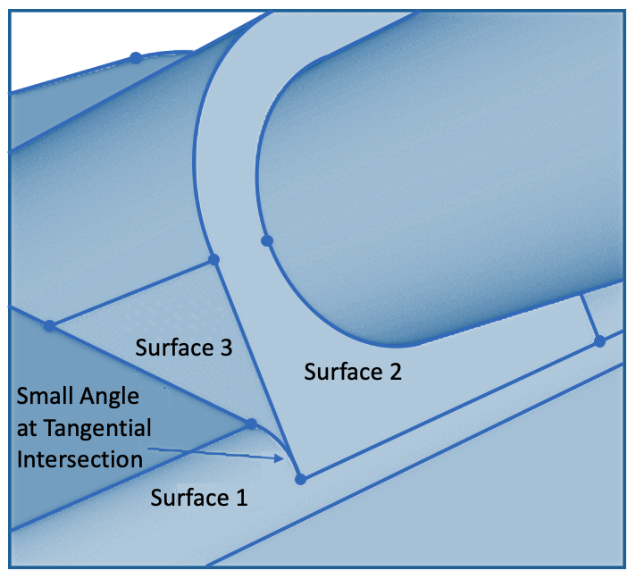
Fig. 6. Tangential Intersection Example
Traits
The tests in the Traits category, group entities according to a specific characteristic of the geometry such as its thickness or radius. Use the threshold values at the top of the Geometry power tools Options panel to set limits on values used to control entities returned from these tests. Geometry Traits include the following:
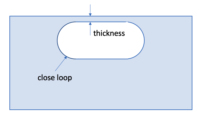
Fig. 7. Close Loop Example
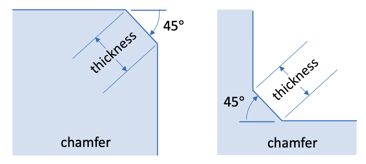
Fig. 8. Chamfer Examples
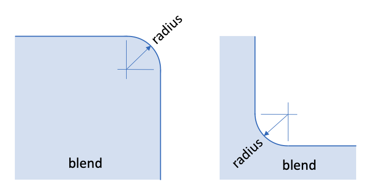
Fig. 9. Blend Examples
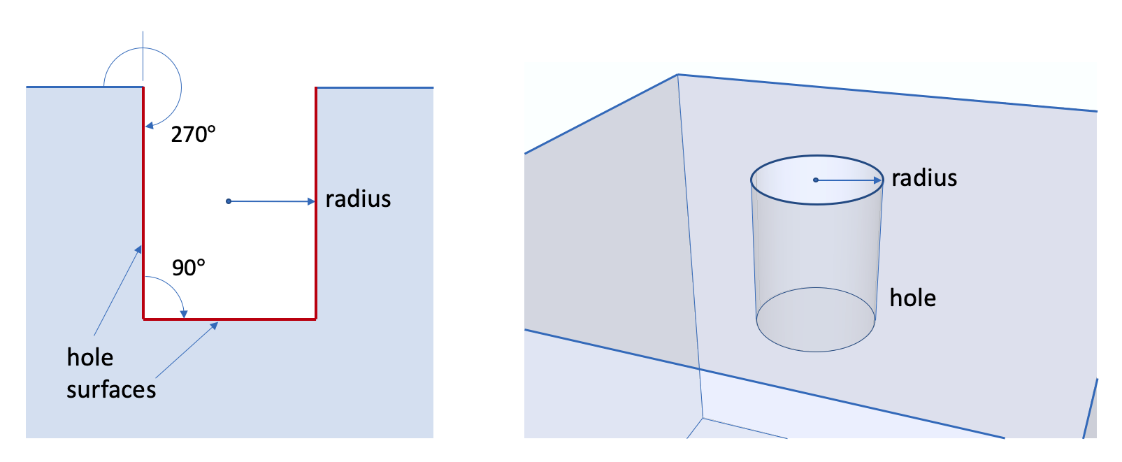
Fig. 10. Hole Example
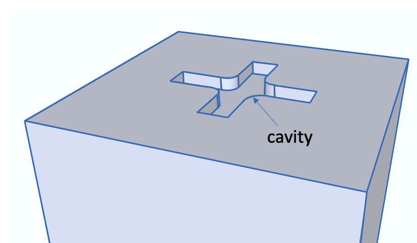
Fig. 11. Cavity Example
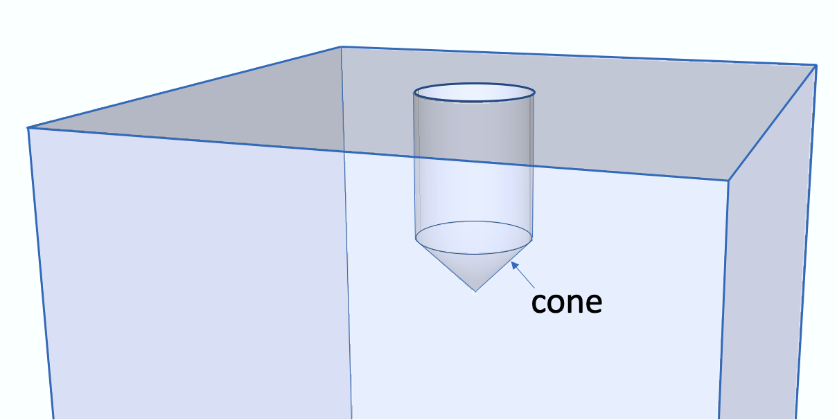
Fig. 12. Cone Example
Assembly Checks
Check the interactions between multiple volumes. Here we check for overlaps, gaps and misalignments between nearby volumes. It will also identify volumes that are in contact as well as entities that are ready for merging.
For assemblies of volumes, it is important to identify if volumes will be connected (imprinted and merged) are in contact, or separated by some distance. The Assembly Checks provide diagnostics and solutions to validate and resolve these interactions.
The Gaps, Overlaps and Misalignments diagnostics normally identify undesirable conditions that must be resolved prior to imprint and merge. Once resolved, the Volume Contacts and Mergable Geometry can be used to validate connections before and after imprinting and merging.
The Options panel also provides a way to estimate or manually set an imprint tolerance. Entities closer than this tolerance will be considered mergable when used with the tolerant imprint command. When the Tolerant Imprint checkbox is selected in the Options panel, the diagnostic tests that identify gaps, overlaps and misalignments will also use the specified tolerance when computing issues.
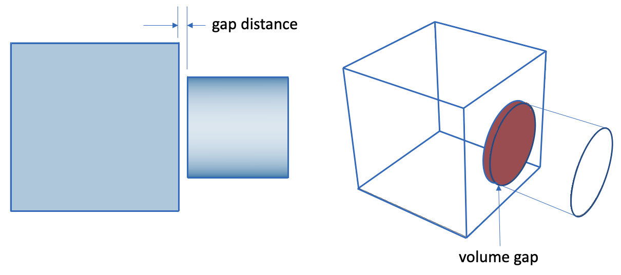
Fig. 13. Volume Gap Example
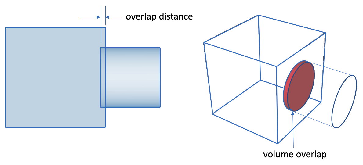
Fig. 14. Volume Overlap Example
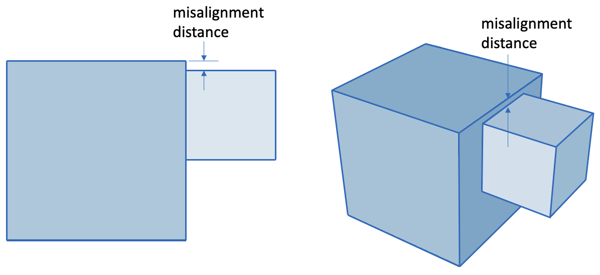
Fig. 15. Volume Misalignment Example
The geometry repair tool buttons appear at the bottom of the Geometry Power Tool. Selecting one of these buttons will bring up the relevant command panel. Tools included in this panel have proven useful for geometry repair and defeaturing.
 Split Surface Button
The split surface tool is used to split a surface into two surfaces. This is useful for blend surfaces, for example, where splitting a surface may facilitate sweeping. To select a surface for splitting, click on the surface in the tree view. To select multiple surfaces in the window, hold the CTRL key* while selecting surfaces (surfaces must be attached to each other). Then press the split surface button to bring up the Control Panel window with the ids of selected surfaces in the text input window. The split surface menu is located on the Control Panel under Geometry-Surface-Modify. You must press the Apply button for the command to be executed. You can also bring up the Split Surface menu by selecting surfaces in the tree view and selecting Split from the right click menu.
*Note: For Mac computers, use the command key (or apple key) to select multiple entities.
 Heal Geometry Button
The healing function in CAE Fidesys is used to improve ACIS geometry that has been corrupted during file import due to differences in tolerances, or inherent limitations in the parent system. These errors may include: geometric errors in entities, gaps between entities, and the absence of connectivity information (topology). To heal a volume, select the volume in the geometry repair tree view. Then press the heal button. You may also press the heal button without a geometry selected in the window, and enter it later. The Control Panel window will come up under the Geometry-Volume-Modify option with the selected volume id highlighted. If no entity is selected, or if another entity type is selected, the input window will be blank. You can also open the healing control panel by selecting Heal from the right click menu in the geometry power tools window.
 Tweak Surface or Curve Button
The tweak command is used to eliminate gaps between entities or simplify geometry. The tweaking commands modify geometry by offsetting, replacing, or removing surfaces, and extending attached surfaces to fill in the gaps. Tweaking can be applied to surfaces, and it can be applied to curves with a valence no more than 2 at each vertex. It can also be applied to some vertices. To tweak a surface, select the surface in the tree view. The Geometry-Surface-Modify control panel will appear with the selected surface id in the input window.
Tweaking is available for curves. Tweaking a curve creates a blended or chamfered edge between two orthogonal surfaces. The curve option is located on the Geometry-Curve-Modify panel under the Blend/Chamfer pull-down option.
Tweaking is also available for some vertices. Tweaking a vertex creates a chamfered or filleted corner between three orthogonal surfaces. The vertex option is located on the Geometry-Vertex-Modify panel under the Tweak pull-down menu.
Note: Only curves with valence 2 or less at each vertex are candidates for tweaking. Any other curve will cause the Geometry-Surface-Modify menu to appear.
 Merge All Mergeable Entities Button
The merge command is used to merge coincident surfaces, curves, and vertices into a single entity to ensure that mesh topology is identical at intersections. Unlike other buttons on the geometry repair panel, the merge button acts as an "Apply" button itself. All geometry that is listed under "mergeable entities" will be merged.
 Remove Entity Button
The remove button is used to simplify geometry by removing unnecessary features. To use the remove feature, click on the surface(s) in the Tree View. Right click and select the Remove Option, or click the Remove icon on the toolbar. The Control Geometry-Surface-Modify control panel will appear, with the surface ids in the input window. The Remove control panel can also be accessed from the right-click menu in the Geometry Power Tools window. Select options and press apply.
 Regularize Entity Button
The regularize button is used to remove unnecessary topology. Regularizing an entity will essentially undo an imprint command.
 Remove Slivers
The remove slivers button is used to remove surfaces with less than a specified surface area. When ACIS removes a surface it extends the adjoining surfaces to fill the gap. If it is not possible to extend the surfaces or if the geometry is bad the command will fail.
 Auto
Clean Geometry
Auto
Clean Geometry
The auto clean button is used to perform automatic cleanup operations on selected geometry. These automatic cleanup operations include forcing sweepable configurations, automatically removing small curves, automatically removing small surfaces, and automatically splitting surfaces.
 Composite Button
The composite button is used to combine adjacent surfaces or curves together using virtual geometry . Virtual geometry is a geometry module built on top of the ACIS representation. Surfaces may be composited to simplify geometry in order to facilitate sweeping and mapping algorithms by removing constraints on node placement. It is important to note that solid model operations such as webcut, imprint, or booleans, cannot be applied to models that have virtual geometry. Both curves and surfaces may be composited.
 Collapse Angle Button
The collapse angle button uses virtual geometry to collapse small angles. This is accomplished by partitioning and compositing surfaces in a way so that the small angle gets merged into a larger angle. Pressing the collapse button on the geometry power tools will open the collapse menu under Geometry-Vertex-Modify control panel. This panel can also be opened by selecting Collapse from the right click menu in the Geometry Tools window.
Collapse Surface Button
Pressing this button will open the collapse surface panel on the main control panel. The collapse surface function uses virtual geometry to eliminate small surfaces on the model to improve mesh quality. It is most useful for blend surfaces.
 Collapse Curve Button
Pressing this button will open the collapse curve panel on the main control panel. The collapse curve command is used to eliminate small curves using virtual geometry.
 Reset the Display Button
The reset graphics button will refresh the graphics window display.
Note: Pressing most of the geometry tool buttons on the panel will only bring up applicable command panels on the Control Panel. You must press the Apply button on the Control Panel to execute the command.
The following right click menu is available from the geometry power tools. Specific options depend on the type of entity selected.
Each of the following menu options are available based on the category and entity type selected. In each case they will open the relevant command panel pre-populated with the entity selected. Select multiple entities prior to selecting the context menu item below to execute the command on multiple entities simulaneously.