Search the documentation
Enter at least 2 characters
Enter at least 2 characters
 |
CAE Fidesys 9.0 Documentation |
This tutorial describes the use of the master tools available in the Fidesys graphical user interface (GUI) for preparing a geometric model for generating a finite element mesh (including corrections and cutting), as well as constructing a mesh. The following capabilities are demonstrated:
Each of these features and the steps to implement them are described in detail in the relevant sections. To work with the tutorial, you need basic knowledge of the Fidesys GUI capabilities, including selecting objects, operating in the graphics window, working with dialog boxes and the Toolbar. If you do not have such knowledge, we recommend that you refer to the initial sections of the User's Guide. Below is the geometric model that will be used in this tutorial.
Note: Some of the steps discussed below involve operations with objects that use their ID numbers. Due to periodic modifications to the Fidesys solid modeling kernel, the built-in rules for assigning IDs to objects may change. Therefore, you should not rely unconditionally on the IDs provided in the tutorial examples. Please pay attention to the data displayed on your screen to determine exactly which entity or ID is being referenced. The model considered in the example is shown in Fig. 1.
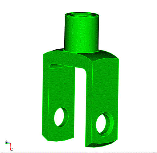
Fig. 1 - Geometric model used in the example.

