Search the documentation
Enter at least 2 characters
Enter at least 2 characters
 |
CAE Fidesys 9.0 Documentation |
The purpose of this task is to calculate the stability coefficient, according to SP 116.13330 «Engineering protection of territories, buildings and structures from dangerous geological processes».
For more information about the implementation of this type of calculation in CAE Fidesys, see the article Strength Reduction Method
The reference for this task is a video. The authors of the video performed the calculation in the Rocscience software package.
1. Create a vertex.
On the command bar, select the module for constructing geometry (Mode — Geometry, Entity — Vertex, Action — Create).
From the list of geometric primitives, select Coordinates.
Set the following parameters:
X Coordinate: 0;.
Y Coordinate: 0;
Z Coordinate: 0.
Click Apply.
2. Create a vertex.
On the command bar, select the module for constructing geometry (Mode — Geometry, Entity — Vertex, Action — Create).
From the list of geometric primitives, select Coordinates.
Set the following parameters:
X Coordinate: 130;.
Y Coordinate: 0;
Z Coordinate: 0.
Click Apply.
3. Create a vertex.
On the command bar, select the module for constructing geometry (Mode — Geometry, Entity — Vertex, Action — Create).
From the list of geometric primitives, select Coordinates.
Set the following parameters:
X Coordinate: 130;.
Y Coordinate: 50;
Z Coordinate: 0.
Click Apply.
4. Create a vertex.
On the command bar, select the module for constructing geometry (Mode — Geometry, Entity — Vertex, Action — Create).
From the list of geometric primitives, select Coordinates.
Set the following parameters:
X Coordinate: 80;.
Y Coordinate: 50;
Z Coordinate: 0.
Click Apply.
5. Create a vertex.
On the command bar, select the module for constructing geometry (Mode — Geometry, Entity — Vertex, Action — Create).
From the list of geometric primitives, select Coordinates.
Set the following parameters:
X Coordinate: 50;.
Y Coordinate: 30;
Z Coordinate: 0.
Click Apply.
6. Create a vertex.
On the command bar, select the module for constructing geometry (Mode — Geometry, Entity — Vertex, Action — Create).
From the list of geometric primitives, select Coordinates.
Set the following parameters:
X Coordinate: 0;.
Y Coordinate: 30;
Z Coordinate: 0.
Click Apply.
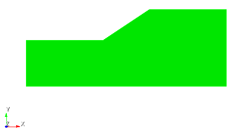
7. Create a surface based on the vertexes.
On the command bar, select the module for constructing geometry (Mode — Geometry, Entity — Surface, Action — Create).

From the list of geometric primitives, select Vertex List.
Set the following parameters:
Vertex ID(s): all.
Click Apply.
1. Set the scheme.
On the command bar, select the surface mesh module (Mode - Mesh, Entity - Surface, Action - Mesh).
Select Trimesh from the list that appears.
Select Surfaces: 1.
Click Apply Scheme.
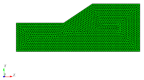
2. Create a finite element mesh.
On the command bar, select the surface mesh module (Mode - Mesh, Entity - Surface, Action - Intervals).
Select Approximate Size from the list that appears.
Select Surfaces: 1;
Approximate Size: 2.
Click Apply Size.
Click Mesh.
1. Create the material.
In the command bar, select the module for specifying material properties (Mode - Material, Entity - Materials Management).

In the widget that opens Materials management, enter the name Material 1 in the middle column.
In the properties column, open the Elasticity section and drag the following parameters from the Isotropic Material subsection to the Material Properties column:
Young's Modulus: 5e+07;
Poisson Ratio: 0.4.
Open the General section and drag the name Density to the Material Properties column.
Set the following parameters:
Density: 2700.
Open the Plasticity section and drag the name Mohr-Coulomb Criterion to the Material Properties column:
Cohesion: 5000;
Internal Friction Angle: 30;
Dilatancy Angle: 0.
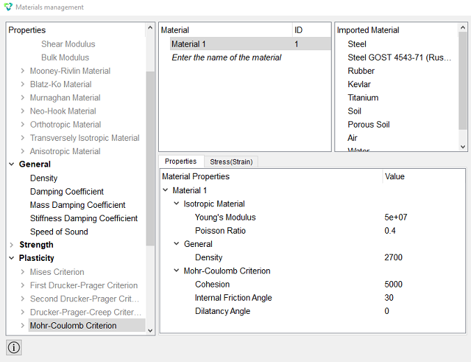
Click Apply.
Close the window Materials management.
2. Create a block.
On the command bar, select the block management module (Mode — Blocks, Entity — Block, Action — Add).

Set the following parameters:
Block ID: 1;
Entity List: Surface;
Entity ID(s): 1.
Click Apply.
3. Set the block parameters.
On the command bar, select the block management module (Mode - Blocks, Entity - Block, Action - Block properties/parameters).

Set the following parameters:
Block ID(s): 1;
Category: Plane;
Material: Material 1;
Coordinate System: Global Cartesian;
Order: 2.
Click Apply.
1. Secure the left and right sides by Х.
On the command panel, select the boundary conditions module (Mode — Boundary Conditions, Entity — Displacement, Action — Create).

Set the following parameters:
Entity List: Curve;
Entity ID(s): 2 6;
Degrees of Freedom: X = 0.
Click Apply.
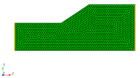
2. Secure the bottom side by Y.
On the command panel, select the boundary conditions module (Mode — Boundary Conditions, Entity — Displacement, Action — Create).
Set the following parameters:
Entity List: Curve;
Entity ID(s): 1;
Degrees of Freedom: Y = 0.
Click Apply.
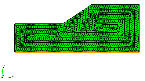
3. Set gravity globally.
On the command panel, select the boundary conditions module (Mode — Boundary Conditions, Entity — Gravity, Action — Create).
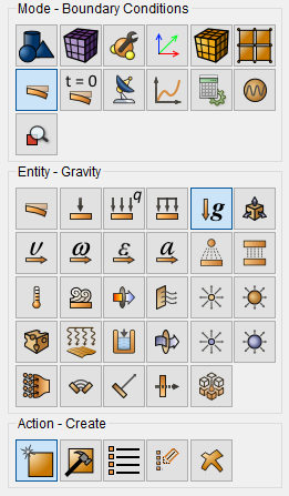
Set the following parameters:
Entity List: Global;
Directions: Y;
Value: -9.81.
Click Apply.
1. Specify the type of task to be solved.
On the command bar, select the calculation settings module (Mode — Calculation, Calculation — Strength Reduction Method).
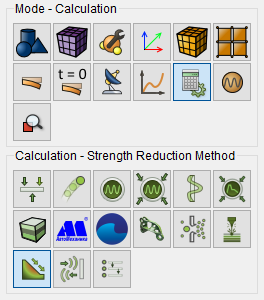
Set the following calculation parameters:
Calculation ID: 1;
Dimencions: 2D;
Start Safety Factor: 1;
Start Increment: 1;
Max Iterations: 50;
Toleranca: 0.001.
Click Apply.
Click Start Calculation.
2. In the window that opens, select the directory where the result will be saved, and enter the file name.
3. After starting the calculation, information about the calculation series will be displayed on the Command line.:
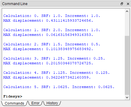
4. In the case of a successful calculation, the console displays the message: Calculation finished successfully at "date" "time".
The result of the calculation will be the SRF coefficient, which is output to the command line:
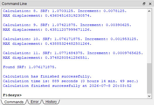
The stability coefficient in CAE Fidesys was Found SRF: 1.076. In Rocscience (the link to the calculation is attached at the beginning of the article) - Critical SRF: 1.09. The difference between the coefficients is 1.3%.
Geometry creating, meshing, setting boundary conditions and materials can be performed using the console interface. Below is a link to the program code that allows you to perform the steps described above manual, you only need to specify the full path and name.