Search the documentation
Enter at least 2 characters
Enter at least 2 characters
 |
CAE Fidesys 9.0 Documentation |
Recall that in the previous step for volumes 1 and 2 (Volume 1, Volume 2) the finite element partitioning scheme was not initially determined automatically - before creating the necessary composite surfaces. Let's set it for these volumes using the Power Tools Panel.
Select the Diagnose Meshability icon.
Click Analyze:
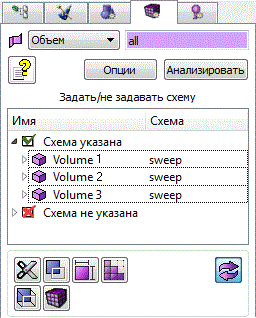
Fig. 45 - Power toolbar, setting the partitioning scheme.
As you can see, the Sweep partitioning scheme is now set for all volumes. The model is ready for partitioning into elements; all volumes are displayed in green:
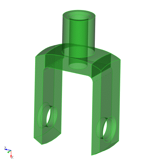
Fig. 46 - Drawing the model after checking for the possibility of constructing a mesh.
Go to the Command Bar. Select Mode - Mesh, Entity - Volume, Action - Intervals.
In the Select Volumes input window, set all.
In the drop-down list below, select Approximate Size.
In the Approximate Size input window, set 2.
Click Apply:
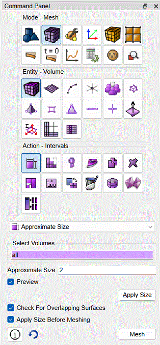
Fig. 47 - Command panel, setting the size of element.
The following image of the model appears in the graphics window with nodes, highlighted in color on all curves forming it:
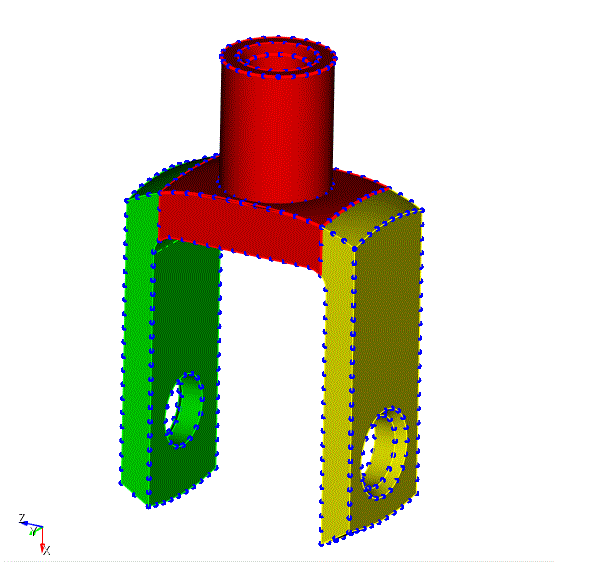
Fig. 48 - Preview of the model's splitting intervals.
With in the Mesh mode and the Volume entity, select Action - Mesh.
Click Mesh (You do not need to click Apply Size, since the scheme has already been set on the Power Tool - Sweep:
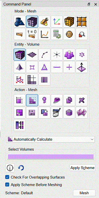
Fig. 49 - Command panel, mesh construction.
The constructed mesh looks like this:
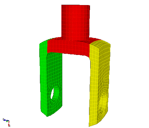
Fig. 50 - Geometric model with hexahedral volumetric mesh built.
Congratulations on completing the GUI Power Tools Tutorial! Click the right arrow below to return to the main page of the Step-by-Step Guides section.

