Search the documentation
Enter at least 2 characters
Enter at least 2 characters
 |
CAE Fidesys 9.0 Documentation |
Composite Geometry are adjacent surfaces that are combined into a single surface. Composite surfaces are created using the Virtual Geometry module, which is a built-in Fidesys geometric kernel that can process existing geometry without changing its constituent entity. The advantage of virtual geometric processing is its reversibility. Virtual geometry can be removed after the finite element mesh has been constructed. The main purpose of using composite surfaces is to overcome the limitations inherent in the applied mesh generation algorithms (schemes). For example, creating a composite surface from two adjacent surfaces allows one to eliminate the requirement that the nodes must be located on a curve belonging to these two surfaces. In the example under consideration, composite surfaces are used taking into account the features of the Stweep algorithm.
On the Power Toolbar, click on the Diagnose Meshability icon.
The drop-down list specifies Volume by default.
In the input window to the right of this list, specify all.
Click Analyze:
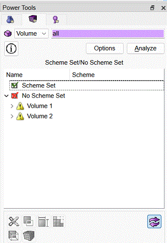
Fig. 34 - Power Tools.
As can be seen from the Scheme Set/Not Scheme Set list located below, only volume 3 (Volume 3) is suitable for automatic splitting (according to the Sweep scheme). For volumes 1 and 2 (Volume 1, Volume 2), the partitioning scheme is not specified, and it is not determined automatically due to the division of each of the two previously existing corner surfaces (see step 5) into a pair of surfaces. Below, we demonstrate the solution to this problem by creating three composite surfaces from a number of initial surfaces and the specified partitioning results.
On the Power Tools, click on the Diagnose Geometry icon.
In the Power Tools menu, press the  (Virtual Geometry, Composite Surface).
Further actions are performed using the Command Bar, which takes the following form:
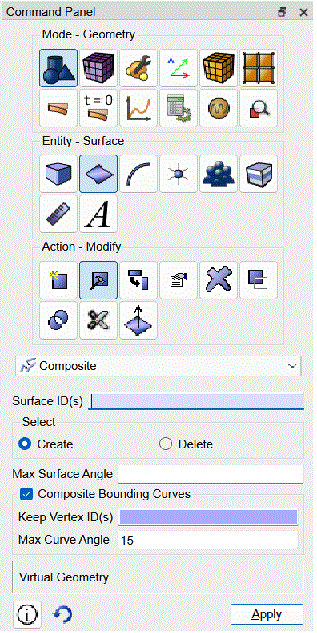
Fig. 35 - Command panel, union of surfaces (virtual geometry).
Note that the geometric model on which these actions are performed looks like this:
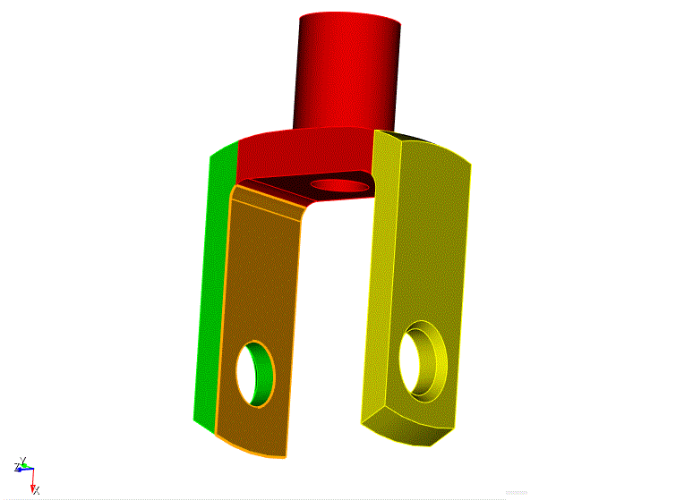
Fig. 36 - Preview of the action of merging surfaces 9 and 25.
In the Surface ID(s) input window, specify 9 and 25 by typing them separated by a space or by making the appropriate selection in the graphics window.
Make sure that the Create button is pressed in the Select radio button group.
Click Apply:
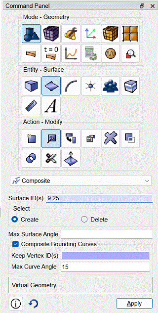
Fig. 37 - Command panel, merging surfaces.
Two surfaces are displayed fused (combined into a composite surface):
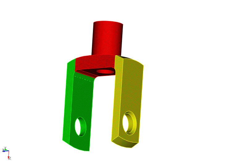
Fig. 38 - Geometric model after merging surfaces 9 and 25.
Repeat the same steps for the opposite side of the model.
Rotate it to make surfaces 6 and 26 visible.
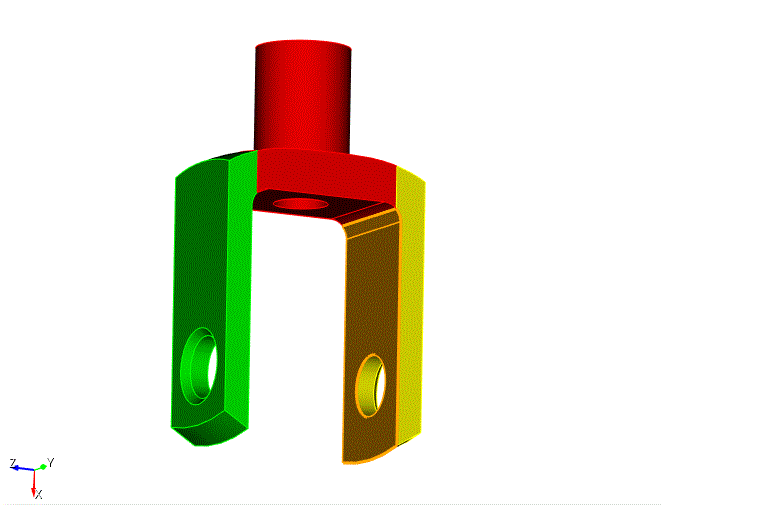
Fig. 39 - Preview of the action of merging surfaces 6 and 26.
In the Surface ID(s) input window, specify 6 and 26.
Click Apply:
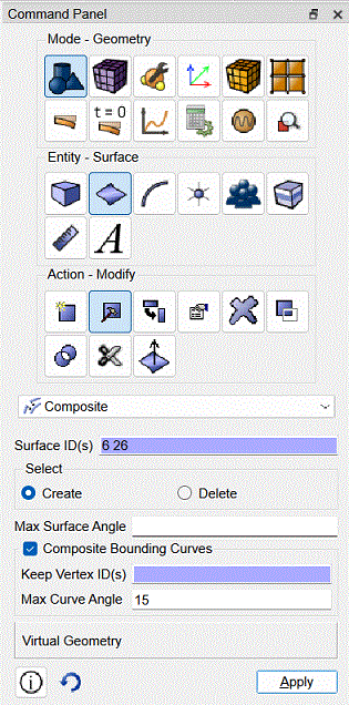
Fig. 40 - Command panel, merging surfaces.
Check that the two surfaces are displayed together:
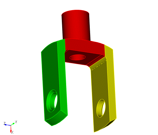
Fig. 41 - Geometric model after merging surfaces 6 and 26.
Finally, we need to create a composite surface from surfaces 24, 44 and 27:
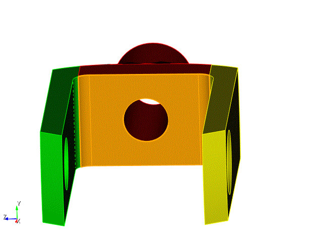
Fig. 42 - Preview of the command to combine surfaces 24, 44 and 27.
As before, this is done using the Command Bar:
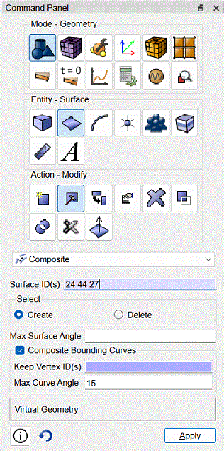
Fig. 43 - Command panel, merging surfaces.
After clicking Apply the result looks like this:
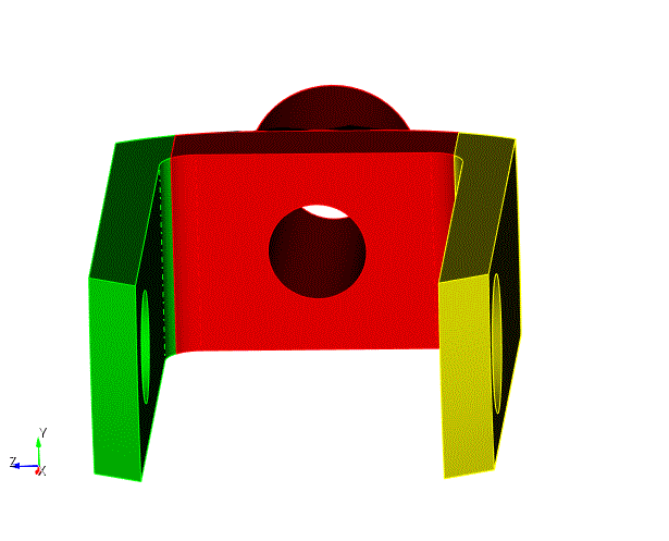
Fig. 44 - Geometric model after merging surfaces and creating virtual geometry.

