Search the documentation
Enter at least 2 characters
Enter at least 2 characters
 |
CAE Fidesys 9.0 Documentation |
The geometric model under consideration has several through holes, so splitting by drawing from one initial surface to one final surface is impossible. It is, however, possible to divide the model into three parts suitable for sweeping. Fig. 18 shows how this should be done. Each of the parts (volumes) obtained by dividing includes one hole.
The volumes are divided by cutting them with a plane. The cutting plane is created by specifying a curve and a vertex through which it must pass.
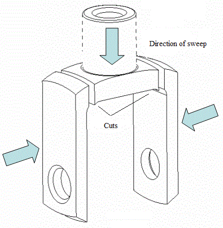
Fig. 18 - Webcut planes and directions of sweeping when constructing a mesh.
For a clearer visualization of the cutting process, switch to the isometric view.
In the menu item Display, select the sub-item View Point, then Isometric:
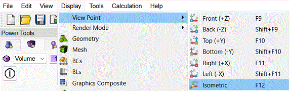
Fig. 19 - Switching to isometric view.
Cuts are made using the Command Bar.
On this bar, select Mode - Geometry, Entity - Volume, Action - Webcut.
In the drop-down list, select the Plane from Curve option:
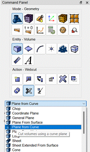
Fig. 20 - Command panel, selection of cutting plane.
Fig. 21 shows the geometry elements that are used to define the cutting plane (Curve 35, Vertex 50). They can be selected in the graphical window by clicking the left mouse button.
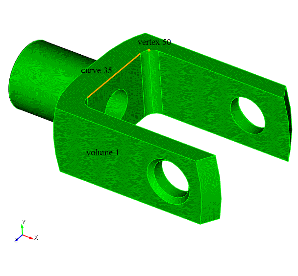
Fig. 21 - Geometry elements that are used to define the cutting plane.
In the Volume ID(s) input window, type 1 or select the volume by clicking.
In the Curve ID input window, specify (in one way or another) 35.
From the Position radio button group, select Near Vertex.
In the Vertex ID, enter 51.
Click Preview.
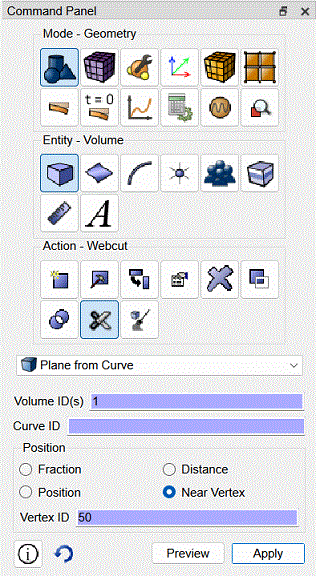
Fig. 22 - Command panel, settings for performing a cut.
A blue cutting plane appears on the isometric view of the model. Make sure that it runs exactly as shown in Fig. 23:
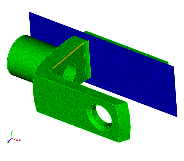
Fig. 23 - Viewing the section plane.
Click Apply.
Volume 1 is now divided into two parts (two volumes). Volume 2 is displayed in yellow on the model view.
Repeat the same steps for the opposite side of the geometric model. The identifiers of the volume (Volume 1) and the curve (Curve 35) remain the same.
In the Vertex ID input box, enter 49.
Click Preview, then Apply.
The final webcut model looks like this:
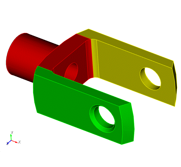
Fig. 24 - View of the model after making a webcut.

