Search the documentation
Enter at least 2 characters
Enter at least 2 characters
 |
CAE Fidesys 9.0 Documentation |
Additive manufacturing is a technology for creating products, which is based on the gradual “building up” of material on a base in the form of a flat platform or axial frame.
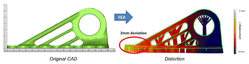
Mathematical modeling of the additive manufacturing process is an important preparatory step in determining the strategy for manufacturing a part. The importance of this stage is primarily justified by the fact that during the production process, the shape of the entity may be distorted due to the peculiarities of the technology, which can lead to going beyond the limits of dimensional tolerances or displacement of functional areas.
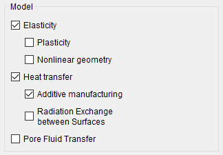
In CAE Fidesys, the calculation for additive printing is located in the Command Panel in the section Calculation Settings - Static - General - check the Heat transfer and Additive manufacturing.
In CAE Fidesys calculation for additive printing is started using commands:
analysis type static elasticity slm dim3
For this calculation, a voxel mesh must be constructed on the model. In CAE Fidesys, this is done using the command voxelmesh. When using this command a block is created for each layer, to which the material must subsequently be assigned.
To set boundary conditions when modeling additive printing in CAE Fidesys needs to use boundary condition Additive Printing:
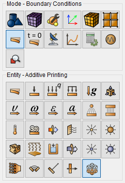
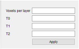
You can also use the voxelbc command:
voxelbc L <value> t0 <value> t1 <value> t2 <value>
L (voxel per layer) - the number of layers added to the calculation in one step (or layer thickness in voxels);
T0 - base (substrate) temperature;
T1 is the temperature of the newly created layer;
T2 - to what temperature the lower layer cools down at the moment of joining the upper one.
Additionally, the voxelbc command:
If necessary, changing/disabling blocks is done manually.
Important: For the alpha version of the calculation, managing blocks and boundary conditions in the steps occurs through the static calculation settings (option Set static load steps count). Calculation starts directly from the Calculation settings section - Static - General - check the box for Heat transfer and Additive manufacturing. Except In addition, the model must be modified in such a way that the layers are built up in the direction of the Z axis.
Command to run additive printing calculations:
analysis type static elasticity heattrans findefs slm dim3
calculation path “D:/calc/path_to_file.pvd”
In the calculation path command you must insert the path to the file calculation *.pvd.
The calculation is started from the static analysis with the Additive Manufactered option (Command Panel - Calculation Settings - Static Analysis).
1. To construct a voxel mesh, voxel sizes x=y=z=0.25 are used. The model was also scaled in meters. And moved so that the layers grow along the Z axis. The result:
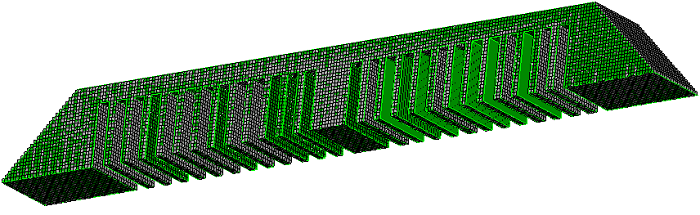
At the same stage, 24 blocks were created (can be checked in the Tree or using the list block all command).
2. You must define a material and assign it to blocks (for example, using the block all material 1 command) or via the GUI.
3. Boundary condition is used Additive printing with parameters:
Thus, one layer is built up in one step (L=1). The total number of steps in step-by-step solution becomes 49. This is ( 2*24+1) .
4. Next, manually add a boundary condition at the last step (fixing middle of the cut layer) and correct the order of block removal.
The fastening at the last step simulates cutting off the “legs”. To do not reassign automatically created blocks, the faces of hexahedrons are fixed in the middle of the cut layer.
5. The calculation is started using the commands:
analysis type static elasticity slm dim3
calculation path "D:\1.pvd"
(The path to the files with the calculation results must be specified independently).
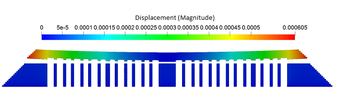
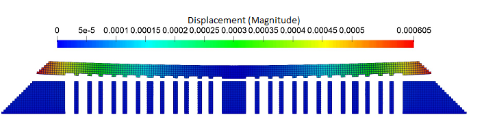
The result of the solution at the last step in the post-processor (deformed view):