Search the documentation
Enter at least 2 characters
Enter at least 2 characters
 |
CAE Fidesys 9.0 Documentation |
There is some initial volume of material. The locations of the constraints are known, as well as the place of application of the load and its value.
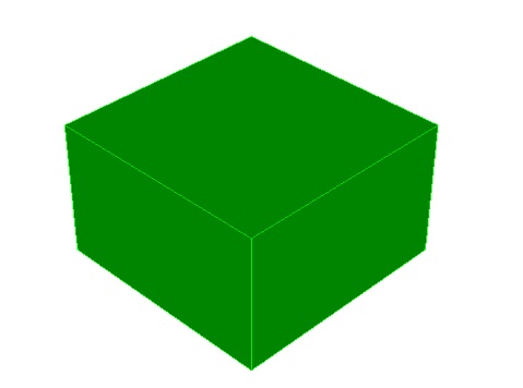
1. Create a brick.
On the command bar, select the module for constructing volume geometry (Mode — Geometry, Entity — Volume, Action — Create).

From the list of geometric primitives, select Brick.
Set the following parameters:
X (width): 10;
Y (heigtht): 6;
Z (depth): 10.
Click Apply.
2. Brick will be created. Next, you need to cut it to create a point of application of the force in the center of the cross section.
On the command bar, select the module for constructing volume geometry (Mode — Geometry, Entity — Volume, Action — WebCut).
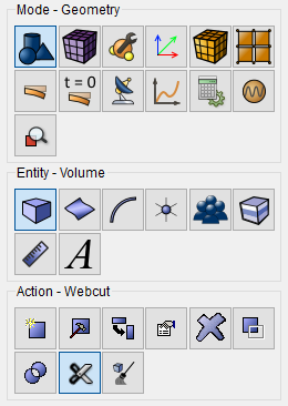
Select Coordinate Plane.
Set the following parameters:
Volume ID(s): all;
Section Plane: ZX;
Offset Value: 0;
Merge.
Сlick Apply.
3. Repeat this procedure for all volumes.
On the command bar, select the module for constructing volume geometry (Mode — Geometry, Entity — Volume, Action — WebCut).
Select Coordinate Plane.
Set the following parameters:
Volume ID(s): all;
Section plane: XY;
Offset Value: 0;
Merge.
Click Apply.
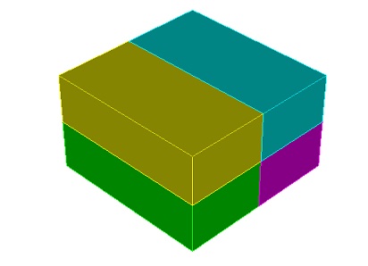
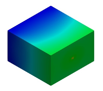
You get the following result.
1. Create a mesh.
On the command bar, select the volume mesh module (Mode — Mesh, Entity — Volume, Action — Intervals).
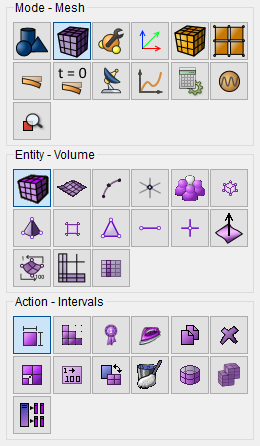
Select Automatic Sizing
Set the following parameters:
Select Volumes: all;
Auto Factor: 3.
Click Apply Size.
Click Mesh.
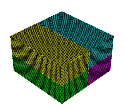
This is the result after the volume has been meshed.
1. Create the material.
In the command bar, select the module for specifying material properties (Mode — Material, Entity — Materials Management).

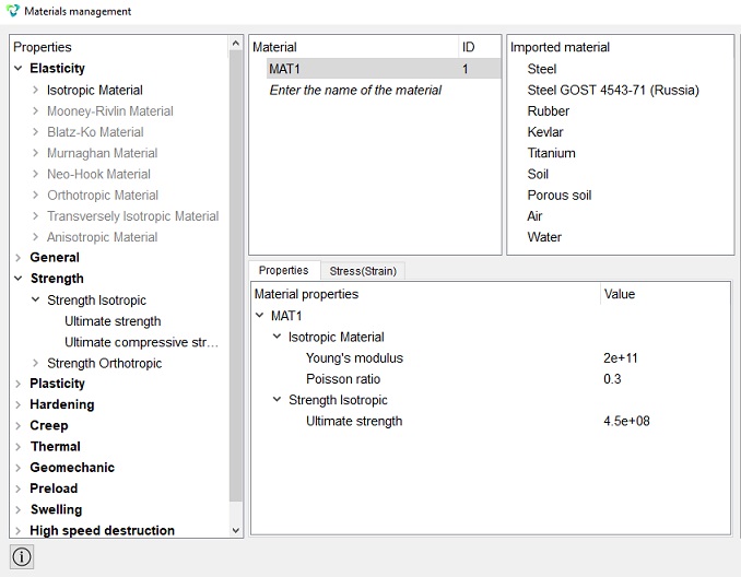
In the Material management widget that opens, in the middle column, specify the material name MAT1. In the properties column, open the Elasticity list and drag the name Isotropic Material into the Material Properties column.
Set the following parameters:
Young's Modulus: 2e+1;
Poisson Ratio: 0.3.
In the left column, go to the Strength section, then Isotropic Strength and select Ultimate strength. Drag it to the right column and enter 4.5e8.
Ultimate strength: 4.5e+08.
Click Apply.
Close the Materials management window.
Important: if the von Mises stresses in your structure are far from the specified value of the ultimate strength, then the optimization algorithm will either leave all the material in place if value of the ultimate strength is too small (when the von Mises stresses in the structure significantly exceed it), or there will be less material than the mesh can show, which will lead to artifacts if value of the ultimate strength is too high (the von Mises stresses in the structure are significantly less than the ultimate strength). It is recommended to preliminarily perform a static calculation and choose a value close to values of the von Mises stresses of most of the structure volume as the ultimate strength, especially if there are stress concentration regions in it, the stress values in which are orders of magnitude greater than the stress values in the main volume.
The next step is to create a block to pass properties to the volume.
2. Create a block.
On the command bar, select the block management module (Mode — Blocks, Entity — Block, Action — Add).

Set the following parameters:
Block ID: 1;
Entity List: Volume;
Entity ID(s): all.
Click Apply.
3. On the command bar, select the block management module (Mode — Blocks,
Entity — Block, Action — Block properties/parameters).

Set the following parameters:
Block Name: Block 1 (ID 1);
Category: Solid;
Material: MAT1;
Coordinate System: Global Cartesian;
Order: 1.
Click Apply.
IMPORTANT: only single-block models are supported for this type of analysis.
1. Create boundary conditions.
On the command panel, select the boundary conditions module (Mode —
Boundary Conditions, Entity — Displacement, Action — Create).

Set the following parameters:
Entity List: Surface;
Entity ID(s): 23 35 29 21;
Degrees Of Freedom: All;
DOF Value: 0.
Click Apply.
2. Apply the force.
Important: The load must be adequate to the strength properties of the material (at the first step of the calculation, the von Mises stresses must not exceed the ultimate strength, so first carry out a static calculation and make sure of this). Otherwise, the algorithm will either leave all the material in place under too much load, or there will be less material than the mesh can reflect, which will lead to artifacts if the load is too low.
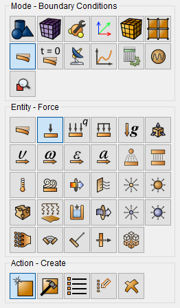
On the command panel, select the boundary conditions module (Mode —
Boundary Conditions, Entity — Force, Action — Create).
Set the following parameters:
Force Entity List: Vertex;
Entity ID(s): 17;
Force: -1e9;
Direction: 0 0 1.
Click Apply.
1. Set the calculation settings.
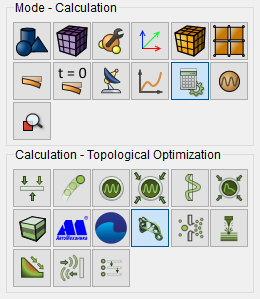
On the command bar, select the calculation settings module (Mode — Calculation Settings, Calculation settings — Topological Optimization).
Set the following parameters:
Dimensions: 3D;
Optimization iterations: 20;
Thickening iterations: 5.
Click Apply.
Click Start Calculation.
2. In the window that appears, select the directory in which the result
will be saved and enter the file name.
3. In the case of a successful calculation, the console displays the message: Calculation finished successfully at "date" "time".
1. Open the file with the results. There are three ways to do that.
Click Ctrl+E.
From the main menu, select Calculation. Click Open Results.
Select Results on Command Panel (Mode - Results). Click Open results.

The FidesysViewer window will appear, where you can view the calculation results.
Apply the "Threshold" filter.
On the command bar, select Filters - Alphabetical - Threshold.
Configure the filter properties:
Input Array: Elasticity Modulus;
Component: Young's modulus;
Minimum: 200000;
Maximum: 200000;
Only cell whose point values are within the range.
Click Apply.
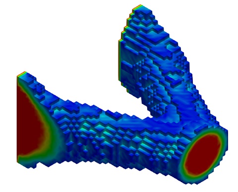
Next, you need to change the following parameters:
Minimum: 1e10;
Maximum: 2e+11.
Click Apply.
If everything was done correctly, you'll see the result in the model window: a topologically optimized design. You can then export it in a 3D printing format.
For a smoother final design, a finer mesh is necessary. To achieve a result ideal for 3D printing, the final element size must be equal to the print layer height. However, in this case, the time required to complete the task may be significant.
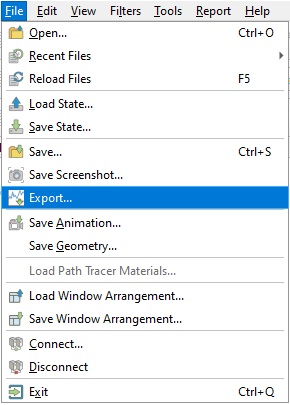
Go to menu File - Export....
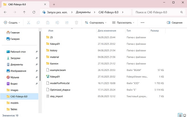
Select the save location and .x3d format and click OK.

Then navigate to the folder with the saved model and double-click to open it. If you have a 3D printer slicer installed, such as Cura, then it will be able to open the model and prepare it for printing.
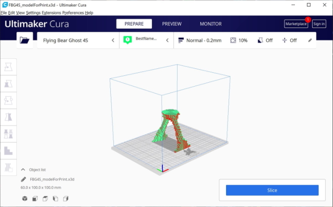
You can also save the model in a format suitable for importing topology back into the preprocessor.
To do this, go to File - Save...
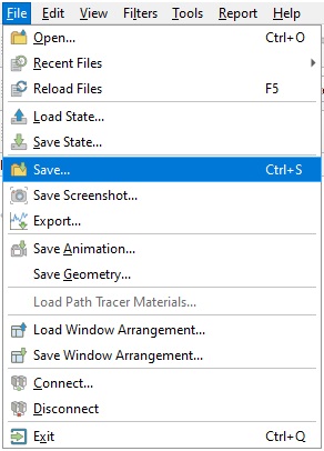
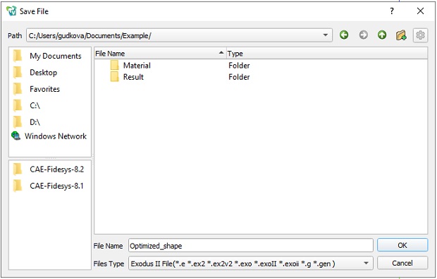
Select a save location and the .e format, and click OK.
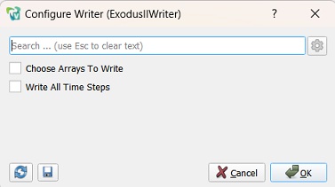
In the window that opens, click OK.
1. Reopen in the preprocessor.
If you haven't closed the preprocessor with the created model, first remove the mesh from it for ease of use.
On the command bar, select the solid geometry module (Mode — Mesh, Entity — Volume, Action — Delete).
Volume ID(s): all.
Click Apply.
If the preprocessor was closed or the model was deleted, it may be possible to first import the topology and then recreate the model on top of it.
2. Import the model.
Go to File - Import...
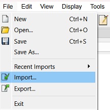
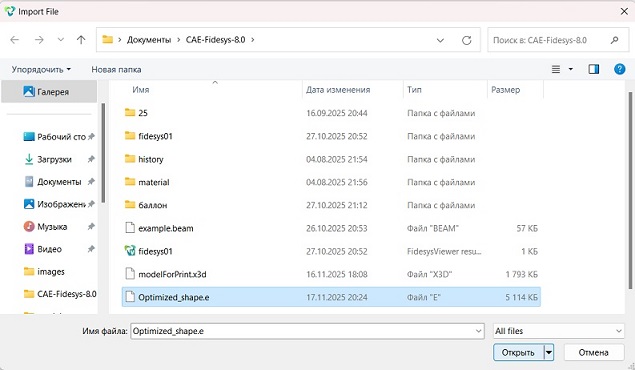
In the window that opens, locate the saved topology file in .e format, select it, and click Open.
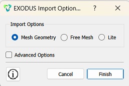
In the next window that opens, select "Mesh Geometry" and click Finish.
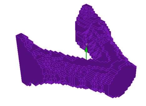
On the screen, you'll see the geometry created from the mesh elements, which you can process to obtain the final part. You can also select the "Free Mesh" import option and process the initial workpiece based on the mesh outline.
Geometry creating, meshing, setting boundary conditions and materials can be performed using the console interface. Below is a link to the program code that allows you to perform the steps described above manual, you only need to specify the full path and name.