Search the documentation
Enter at least 2 characters
Enter at least 2 characters
 |
CAE Fidesys 9.0 Documentation |
We solve the 3D problem of a hollow two-material cylinder the inner and outer surfaces of which undergo convection.
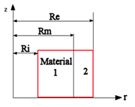
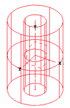
The pictures represent a geometric model of the problem.
The inner radius of the cylinder Ri = 0.30 m, the middle radius of the cylinder (at the place of material changing) Rm = 0.35 m, the external radius of the cylinder Re = 0.37 m.
Сonvective heat exchange with internal temperature Ti = 70 ° C and coefficient hi = 150 W/ m2/°C occurs on the inner surface of the cylinder. Сonvective heat exchange with exterior temperature Te = -15 °C and coefficient he = 200 W/ m2/°C occurs on the outer surface of the cylinder.
Materials are isotropic. The material heat transfer 1 is Ѵ1 = 40 W/(m·°C). The material heat transfer 2 is Ѵ2 = 20 W/(m·°C).
Test pass criterion is the following:
at the point (0.3, 0, 0) heat flux 6687 W/ m2 is within 1%.
1. Create the first cylinder.
On the command bar, select the module for constructing volume geometry (Mode – Geometry, Entity – Volume, Action – Create).

Select Cylinder in the list of geometric elements.
Specify the cylinder dimensions:
Click Apply.
2. Create the second cylinder.
On the command bar, select the module for constructing volume geometry (Mode — Geometry, Entity — Volume, Action — Create). Select Cylinder in the list of geometric elements.
Specify the cylinder dimensions:
Click Apply.
3. Create the third cylinder.
On the command bar, select the module for constructing volume geometry (Mode — Geometry, Entity — Volume, Action — Create). Select Cylinder in the list of geometric elements.
Specify the cylinder dimensions:
Click Apply.
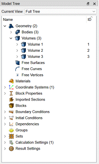
As a result, three generated entities are displayed in the Model Tree (Volume 1, Volume 2 and Volume 3).
4. Subtract the first cylinder from the second one.
On the command bar, select the module for constructing volume geometry (Mode — Geometry, Entity — Volume, Action — Boolean).
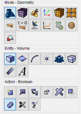
Select Subtract in the list of operations.
Set the following parameters:
Click Apply.
5. Subtract the second cylinder from the third one.
On the command bar, select the module for constructing volume geometry (Mode — Geometry, Entity — Volume, Action — Boolean). Select Subtract in the list of operations.
Set the following parameters:
Click Apply.
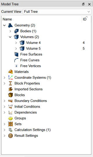
As a result, five generated entities are displayed in the Model Tree: Volume 1, Volume 2, Volume 3, Volume 4 and Volume 5. Delete the thirst three bodies by right-clicking and selecting Delete.
Two entities: Volume 4 and Volume 5 are left in the Model Tree.
6. Merge obtained entities.
On the command bar, select the module for constructing volume geometry (Mode — Geometry, Entity — Volume, Action — Imprint and Merge).
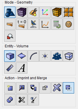
Select Merge Volumes in the list of operations.
Set the following parameters:
Click Apply.
1. On the command bar, select the mesh module (Mode — Mesh, Entity — Curve, Action — Mesh).

Specify the parameters of mesh refinement:
Click Apply Size.
2. On the command bar, select the volume mesh module (Mode — Mesh, Entity — Volume, Action — Mesh).
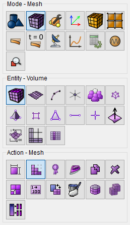
Specify the mesh refinement level:
Click Apply Scheme.
Click Mesh.
1. Create Material 1.
In the command bar, select the module for specifying material properties (Mode — Blocks, Entity — Materials Management).

Specify the name of the material. Material 1. Drag from the left column to the section Thermal of the label Thermal isotropic in the Material Properties column.
Set the following parameters:
Click Apply.
2. Create Material 2.
Select setting the material properties section on Command Panel (Mode — Blocks, Entity — Materials Management).
Specify the name of the material. Material 2. Drag from the left column to the section Thermal of the label Thermal isotropic in the Material Properties column.
Set the following parameters:

Click Apply.
Close the Materials management window.
3. Create Block 1.
On the command bar, select the block management module (Mode — Blocks, Entity — Block, Action — Add).

Set the following parameters:
Click Apply.
4. Create Block 2.
On the command bar, select the block management module (Mode — Blocks, Entity — Block, Action — Add).
Set the following parameters:
Click Apply.
5. Set parameters for block № 1.
On the command bar, select the block management module (Mode - Blocks, Entity - Block, Action - Block properties/parameters).

Set the following parameters:
Block ID(s): 1;
Category: Solid;
Material: Material 1;
Coordinate System: Global Cartesian;
Order: 1.
Click Apply.
6. Set parameters for block № 2.
On the command bar, select the block management module (Mode - Blocks, Entity - Block, Action - Block properties/parameters).
Set the following parameters:
Block ID(s): 2;
Category: Solid;
Material: Material 2;
Coordinate System: Global Cartesian;
Order: 1.
Click Apply.
1. Set the process of convective heat exchange on the inner surface of the cylinder.
On the command panel, select the boundary conditions module (Mode — Boundary Conditions, Entity — Convection, Action — Create).
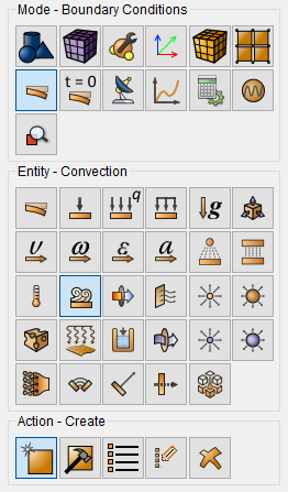
Set the following parameters:
Entity List: Surface;
Entity ID(s): 10;
Select the way of parameters setting: Surrounding;
Temperature: 70;
Coefficient: 150.
Click Apply.
2. Set the process of convective heat exchange on the outer surface of the cylinder.
On the command panel, select the boundary conditions module (Mode — Boundary Conditions, Entity — Convection, Action — Create).
Set the following parameters:
Entity List: Surface;
Entity ID(s): 15;
Select the way of parameters setting: Surrounding;
Temperature: -15;
Coefficient: 200.
Click Apply.
3. Fix the base of the cylinder.
On the command panel, select the boundary conditions module (Mode — Boundary Conditions, Entity — Displacement, Action — Create).

Set the following parameters:
Entity List: Surface;
Entity ID(s): 12 13 16 17 (using space after each of them);
Degrees of Freedom: Z.
Click Apply.
1. Set the type of the problem to be solved.
On the command bar, select the calculation settings module (Mode — Calculation Settings, Calculation Settings — Static, Static — General).

Set the solver settings:
Dimensions: 3D;
Model: Elasticity
Model: Heat Transfer.
Click Apply.
2. In a pop-up window select a folder to save the result and enter the file name.
3. In the case of a successful calculation, the console displays the message: Calculation finished successfully at "date" "time".
1. Open the file with the results. There are three ways to do that.
Click Ctrl+E.
From the main menu, select Calculation. Click Open Results.
Select Results on Command Panel (Mode - Results). Click Open results.

2. Display the component of the heat flux.
In FidesysViewer window set the following parameters on Toolbar:
Representation Field: Heat Flux;
Representation Mode: Surface.

 To display the color legend scale, click the button
Toggle Color Legend Visibility on Command Panel.
To display the color legend scale, click the button
Toggle Color Legend Visibility on Command Panel.
3. Select a point where you need to view the heat flux.
In the Main Menu, select the filter Probe Location. In the tab Properties set the coordinates of the point A where you need to view the stress:
Show Sphere;
Center: 0.3 0 0;
Radius: 0;
Number Of Points: 1.
Click Apply.
 To apply all of the filters changes automatically,
click Apply changes to parameters automatically on Command
Panel.
To apply all of the filters changes automatically,
click Apply changes to parameters automatically on Command
Panel.
As a result, point A is displayed at the picture.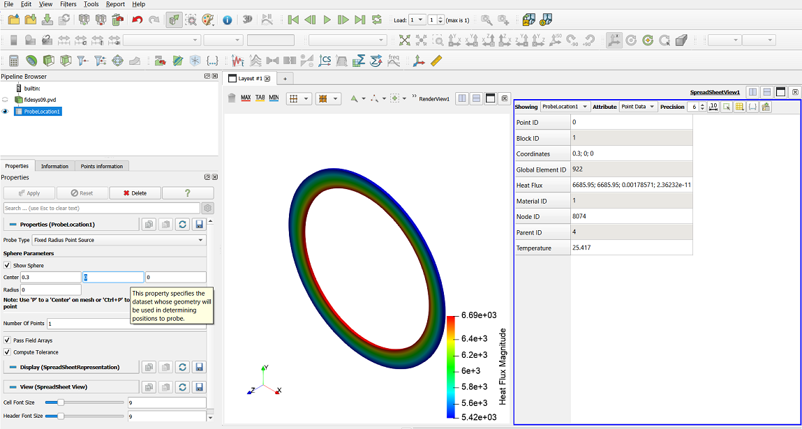
4. View a numerical value of the heat flux at the selected point A.
See the heat flux values in the line Heat Flux in the tab Information in the field Data Arrays.
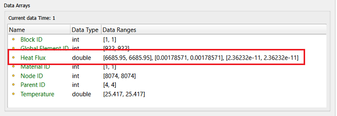
The heat flux value is calculated using the following formula:

The difference between the obtained value 6686.41 and the required one 6 687 is 0.01%.
5. Download numerical data.
Select File Save Data in the Main Menu or click Ctrl+S. Enter the file name (*.csv format), leave it by default. Click ОК. The saved file is an ordinary table of numerical data which can be opened in any text editor.
Geometry creating, meshing, setting boundary conditions and materials can be performed using the console interface. Below is a link to the program code that allows you to perform the steps described above manual, you only need to specify the full path and name.