Search the documentation
Enter at least 2 characters
Enter at least 2 characters
 |
CAE Fidesys 9.0 Documentation |
In the proposed problem, a steel cylinder is pressed into an aluminum block. Both materials are assumed to be linearly elastic. At the same time, per cylinder a point force F acts in the negative direction of the Y-axis. Control the task is designed to check correctness:
setting parameters of sliding contact without friction in the interface;
static solution with sliding contact without friction for 2D models;
the correctness of the output of the Strees field in the contact.
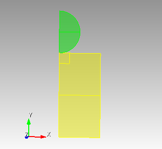
1. Create a circle with a radius of 50.
On the command bar, select the module for constructing surface geometry (Mode — Geometry, Entity — Surface, Action — Create).

From the list of geometric primitives, select Circle.
Set the following parameters:
Specify Circle Using: Radius;
Radius: 50;
ZPlane.
Click Apply.
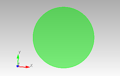
2. Create a rectangle.
On the command bar, select the module for constructing surface geometry (Mode — Geometry, Entity — Surface, Action — Create).
From the list of geometric primitives, select Rectangle.
Set the following parameters:
Width: 200;
Height: 200;
ZPlane.
Click Apply.
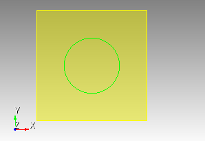
3. Move the rectangle.
On the command bar, select the module for constructing surface geometry (Mode — Geometry, Entity — Surface, Action — Transform).
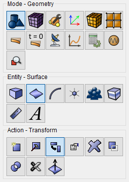
From the list of actions, select Move.
Set the following parameters:
Surface ID(s): 2;
Include Merged;
Select Method: Distance;
Y Distance: -150.
Click Apply.
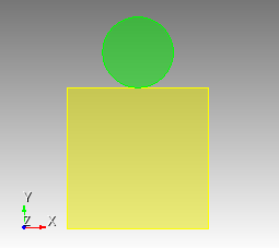
4. Cut both surfaces in half
On the command bar, select the module for constructing surface geometry (Mode — Geometry, Entity — Surface, Action — Webcut).
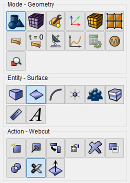
From the list, select Coordinate Plane.
Set the following parameters:
Body ID(s): 1 2;
YZ.
Click Apply.
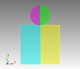
5. Remove clipped surfaces.
On the command bar, select the module for constructing surface geometry (Mode - Geometry, Entity — Surface, Action — Delete).
Set the following parameters:
Surface ID(s): 4 6.
Click Apply.
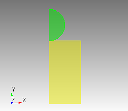
6. Divide the semicircle in two.
On the command bar, select the module for constructing surface geometry (Mode - Geometry, Entity — Surface, Action — Modify).
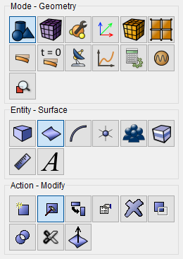
From the list, select Split.
Set the following parameters:
By Location;
Surface ID(s): 3
First Split Location:
Position (X,Y,Z): 0 0 0;
Second Split Location:
Position (X,Y,Z): 50 0 0.
Click Apply.
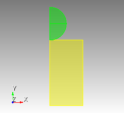
7. Create a rectangle.
On the command bar, select the module for constructing surface geometry (Mode — Geometry, Entity — Surface, Action — Create).
From the list of geometric primitives, select Rectangle.
Set the following parameters:
Width: 25;
ZPlane.
Click Apply.
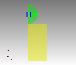
8. Move the rectangle.
On the command bar, select the module for constructing surface geometry (Mode — Geometry, Entity — Surface, Action — Transform).
From the list of actions, select Move.
Set the following parameters:
Surface ID(s): 9;
Include Merged;
Select Method: Distance;
Y Distance: -62.5.
Click Apply.
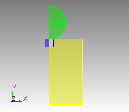
9. Move the rectangle.
On the command bar, select the module for constructing surface geometry (Mode — Geometry, Entity — Surface, Action — Transform).
From the list of actions, select Move.
Set the following parameters:
Surface ID(s): 9;
Include Merged;
Select Method: Distance;
Y Distance: 12.5.
Click Apply.
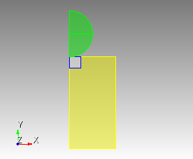
10. Divide two rectangles.
On the command bar, select the module for constructing surface geometry (Mode - Geometry, Entity — Surface, Action — Modify).
From the list, select Split.
Set the following parameters:
With Surface;
Surface ID(s): 5;
With Surface ID(s): 9.
Click Apply.
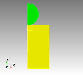
11. Remove the surface.
On the command bar, select the module for constructing surface geometry (Mode - Geometry, Entity — Surface, Action — Delete).
Set the following parameters:
Surface ID(s): 5.
Click Apply.
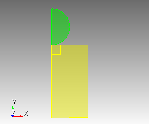
12. Divide the rectangle in two.
On the command bar, select the module for constructing surface geometry (Mode - Geometry, Entity — Surface, Action — Modify).
From the list, select Split.
Set the following parameters:
By Location;
Surface ID(s): 11;
First Split Location:
Position (X,Y,Z): 0 -150 0;
Second Split Location:
Position (X,Y,Z): 100 -150 0.
Click Apply.
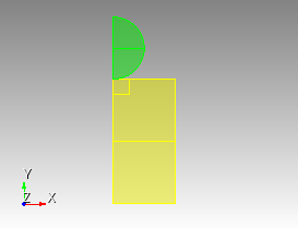
1. Mesh curves for a semicircle.
On the command bar, select the mesh module (Mode — Mesh, Entity – Curve, Action – Mesh).

Set the following parameters:
Select Curves: 17 18;
Bias;
First Size & Bias;
First Size: 0.25;
Bias Factor: 1.025;
Start Vertex ID: 7.
Click Apply Size.
Click Mesh.
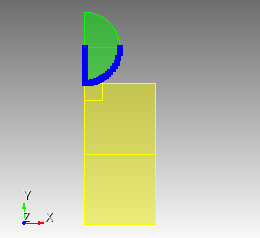
2. Create a mesh for a portion of the surface of a semicircle.
On the command bar, select the surface mesh module (Mode — Mesh, Entity – Surface, Action – Intervals).
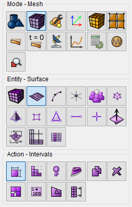
From the list of actions, select Automatic Sizing.
Select Surfaces: 7;
Auto Factor: 3.
Click Apply Size.
Click Mesh.
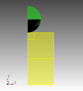
3. Create a mesh for a portion of the surface of a semicircle.
On the command bar, select the surface mesh module (Mode — Mesh, Entity – Surface, Action – Intervals).
From the list of actions, select Automatic Sizing.
Select Surfaces: 8;
Auto Factor: 3.
Click Apply Size.
Click Mesh.
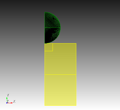
4. Create a mesh the square.
On the command bar, select the surface mesh module (Mode — Mesh, Entity – Surface, Action – Intervals).
From the list of actions, select Approximate Size.
Select Surfaces: 10;
Approximate Size: 1.
Click Apply Size.
Click Mesh.
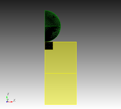
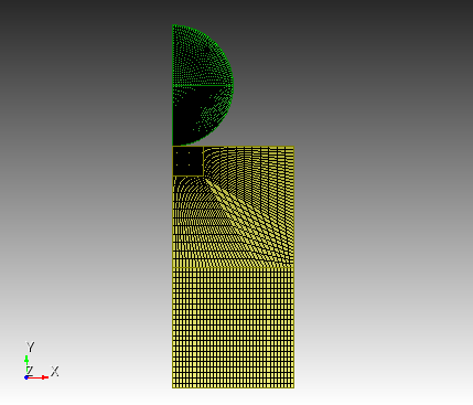
5. Create a mesh the rectangle.
On the command bar, select the surface mesh module (Mode — Mesh, Entity – Surface, Action – Intervals).
From the list of actions, select Automatic Sizing.
Select Surfaces: 13 12;
Auto Factor: 3.
Click Apply Size.
Click Mesh.
1. Set the first material.
OIn the command bar, select the module for specifying material properties (Mode — Material, Entity — Materials Management).

In the column "Material" enter the name of the material Mat_cube.
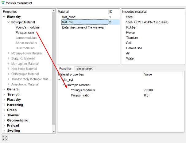
In the Material Properties column, select the created material, and then drag the desired properties to it from the left column.
Drag properties and specify their value:
Young's Modulus: 2.1e5;
Poisson Ratio: 0.3.
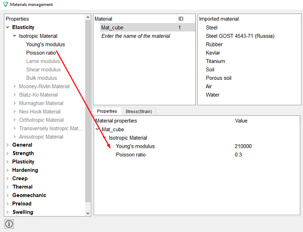
Click Apply.
Close the Materials management window.
2. Set the second material.
On the command panel, select (Mode — Material, Entity — Materials Management).
In the column "Material" enter the name of the material Mat_cyl.
In the Material Properties column, select the created material, and then drag the desired properties to it from the left column.
Drag properties and specify their value:
Young's Modulus: 7e4;
Poisson Ratio: 0.3.
Click Apply.
3. Create the first block for the square and rectangle.
On the command bar, select the block management module (Mode — Blocks, Entity – Block, Action – Add).

Entity List: Surface;
Entity ID(s): 2 13 10.
Click Apply.
4. Create a second block for the semicircle.
On the command bar, select the block management module (Mode — Blocks, Entity – Block, Action – Add).
Entity List: Surface;
Entity ID(s): 7 8.
Click Apply.
5. Set the parameters of the first block.
On the command bar, select the block management module (Mode - Blocks, Entity - Block, Action - Block properties/parameters).

Set the following parameters:
Block ID(s): 1;
Category: Plane;
Material: Mat_cube;
Coordinate System: Global Cartesian;
Order: 2.
Click Apply.
6. Set the parameters of the second block.
On the command bar, select the block management module (Mode - Blocks, Entity - Block, Action - Block properties/parameters).
Set the following parameters:
Block ID(s): 1;
Category: Plane;
Material: Mat_cyl;
Coordinate System: Global Cartesian;
Order: 2.
Click Apply.
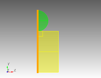
1. Fix the curve in All.
On the command panel, select the boundary conditions module (Mode — Boundary Conditions, Entity — Displacement, Action — Create).

Set the following parameters:
Entity List: Curve;
Entity ID(s): 11;
Degrees of Freedom: All;
DOF Value: 0.
Click Apply.
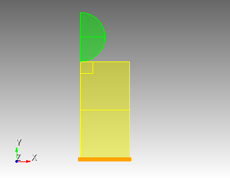
2. Anchor the curves based on the symmetry condition.
On the command panel, select the boundary conditions module (Mode — Boundary Conditions, Entity — Displacement, Action — Create).
Set the following parameters:
Entity List: Curve;
Entity ID(s): 20 17 28 35 32;
Degrees of Freedom: X-Translation Disp, Z-Translation Disp, X-Rotation Disp, Y-Rotation Disp, Z-Rotation Disp;
DOF Value: 0.
Click Apply.
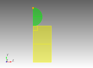
3. Apply force to the top of the semicircle.
On the command panel, select the boundary conditions module (Mode — Boundary Conditions, Entity — Force, Action — Create).
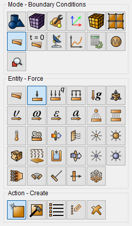
Set the following parameters:
Force Entity List: Vertex;
Entity ID(s): 6;
Force: 17500;
Direction: ny.
Click Apply.
4. Set the contact condition.
On the command panel, select the boundary conditions module (Mode — Boundary Conditions, Entity — Contact, Action — Create).
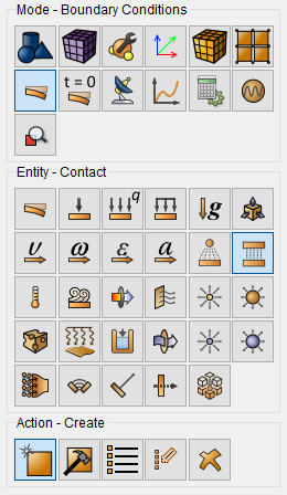
Set the following parameters:
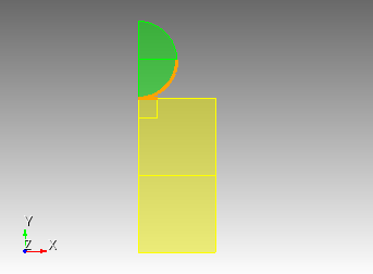
Master and Slave selection;
Master Entity List: Curve;
Entity ID(s): 27;
Slave Entity List: Curve;
Entity ID(s): 18;
Type: General;
Tolerance: 0.0005;
Method: Penalty;
Normal Stiffness: 1;
Tangent Stiffness: 0.5.
Click Apply.
1. Set the type of problem you want to solve.
On the command bar, select the calculation settings module (Mode — Calculation Settings, Calculation Settings — Static, Static — General).

Please select:
Dimension: 2D;
Plain state: Plane strain;
Model: Elasticity.
Click Apply.
Click Start Calculation.
2. In a pop-up window select a folder to save the result and enter the file name.
3. In the case of a successful calculation, the console displays the message: Calculation finished successfully at "date" "time".
1. Open the file with the results. There are three ways to do that.
Click Ctrl+E.
From the main menu, select Calculation. Click Open Results.
Select Results on Command Panel (Mode - Results). Click Open results.

The FidesysViewer window will appear, in which you can view the calculation results.
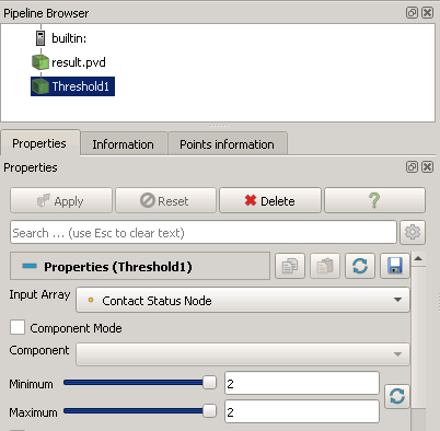
2. On the standard line, select Filters - Alphabetical - Threshold.

Set the following parameters:
Input Array: Contact Status Node;
Minimum: 2;
Maximum: 2.
Click Apply.
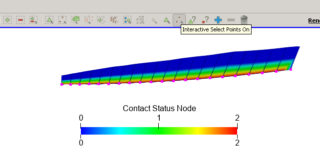
3. From the main panel of FidesysViewer, click Interactive Select Points On.
Select points on the geometric model that lie on the contact curve blocks.
On the standard line, select Filters - Alphabetical - Extract Selection.
Click Apply.
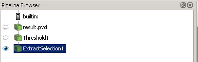
The tree view becomes as follows:
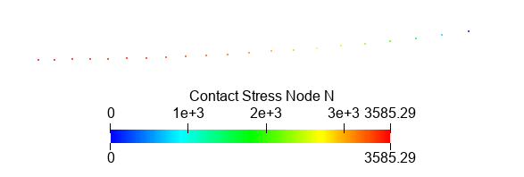
Display the N component of the Contact Node Strees field.

The result will be as follows:
4. On the standard line, select Filters - Alphabetical - Extract Selection.
Click Apply.
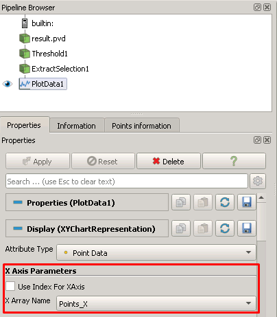
X Axis Parameters: remove the flag;
X Array Name: Points_X.
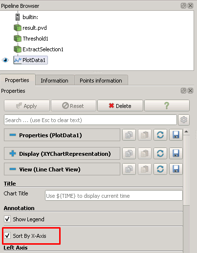
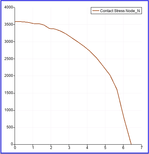
Recommendation: Set the flag "Sort By X-Axis", to get a more accurate graph. The result will look like this way:
Geometry creating, meshing, setting boundary conditions and materials can be performed using the console interface. Below is a link to the program code that allows you to perform the steps described above manual, you only need to specify the full path and name.