Search the documentation
Enter at least 2 characters
Enter at least 2 characters
 |
CAE Fidesys 9.0 Documentation |
We consider the plane problem of formation in a preloaded, infinitely extended body (the mechanical properties of the material of which are described by the Murnaghan potential) circular at the time of inclusion. The mechanical properties of the inclusion material are described by the Murnaghan potential. A variant of the model of the formation of an elastic inclusion is considered, which (at the moment of formation) completely repeats the shape of the remote part of the body in the case where when forces acting on the surface of the inclusion are opposite to the forces acting on the newly formed boundary of the body (through material replacement step by step).
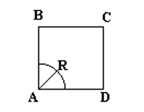
1. Create a plate.
On the command bar, select the module for constructing surface geometry (Mode — Geometry, Entity — Surface, Action — Create).

From the list of geometric primitives, select Rectangle.
Set the following parameters:
Width: 100;
ZPlane.
Click Apply.
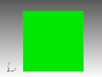
2. Create an ellipse.
On the command bar, select the module for constructing surface geometry (Mode — Geometry, Entity — Surface, Action — Create).
From the list of geometric primitives, select Ellipse.
Set the following parameters:
Specify Ellipse Using: Radius;
Major Radius: 0.5;
Minor Radius: {0.5-0.005601016};
ZPlane.
Click Apply.
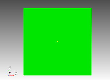
3. Subtract an ellipse from the plate.
On the command bar, select the module for constructing surface geometry (Mode — Geometry, Entity — Surface, Action — Boolean).
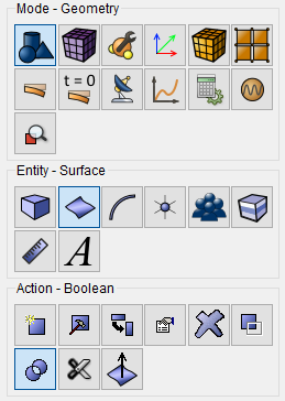
From the list, select Subtract.
Set the following parameters:
A Surface ID(s): 1;
В Surface ID(s): 2;
Keep Originals;
Keep В.
Click Apply.
4. Cut the model into 2 pieces.
On the command bar, select the module for constructing surface geometry (Mode — Geometry, Entity — Surface, Action — Webcut).
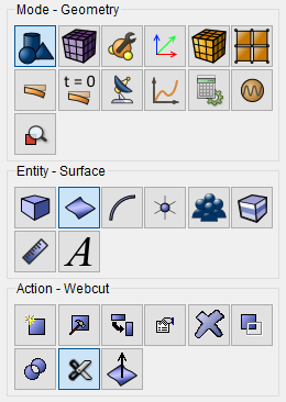
From the list, select Coordinate Plane.
Set the following parameters:
Body ID(s): all;
With Plane: YZ;
Offset Value: 0.
Click Apply.
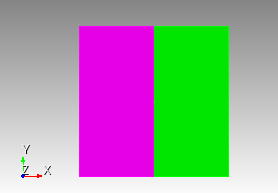
5. Cut the model into 2 pieces.
On the command bar, select the module for constructing surface geometry (Mode — Geometry, Entity — Surface, Action — Webcut).
From the list, select Coordinate Plane.
Set the following parameters:
Body ID(s): all;
ZХ;
Offset Value: 0.
Click Apply.
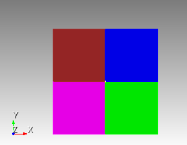
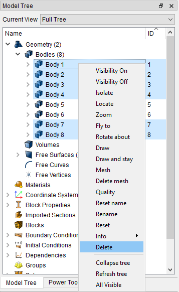
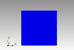
6. Remove the body so that there is a quarter of the plate and a quarter of the ellipse inside it.
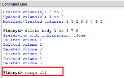
In the Model Tree, select (Geometry — Body). Select bodies: 1 2 3 4 7 8. Right click and select Delete.
7. Merge surfaces.
In the Command Line enter "merge all".
Click Enter.
1. Create a mesh for the ellipse.
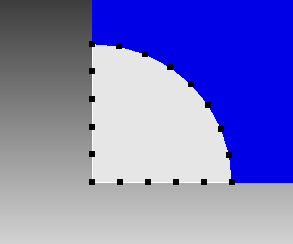
On the command bar, select the mesh module (Mode — Mesh, Entity – Curve, Action – Mesh).

Set the following parameters:
Select Curves: 30 32 26;
Equal;
Approximate Size;
Approximate Size: 0.1.
Click Apply Size.
Click Mesh.
2. Mesh the surface of the ellipse.
On the command bar, select the surface mesh module (Mode — Mesh, Entity – Surface, Action – Intervals).
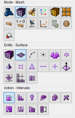
From the list of actions, select Automatic Sizing.
Select Surfaces: 11;
Auto Factor: 5.
Click Apply Size.
Click Mesh.
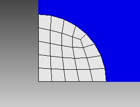
3. Mesh the plate.
On the command bar, select the mesh module (Mode — Mesh, Entity – Curve, Action – Mesh).
Set the following parameters:
Select Curves: 24 7;
Bias;
First Size & Bias;
First Size: 0.1;
Bias Factor: 1.09;
Start Vertex ID: 22 8.
Click Apply Size.
Click Mesh.
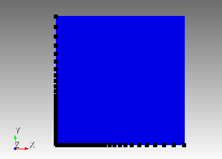
4. Mesh the surface.
On the command bar, select the surface mesh module (Mode — Mesh, Entity – Surface, Action – Intervals).
From the list of actions, select Automatic Sizing.
Select Surfaces: 9;
Auto Factor: 5.
Click Apply Size.
Click Mesh.
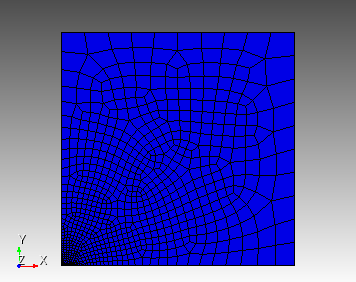
1. Specify the material for the plate.
In the command bar, select the module for specifying material properties (Mode — Material, Entity — Materials Management).

In the column Material enter the name of the material Matrix.
In the Material Properties column, select the created material, and then drag the desired properties to it from the left column.
Drag properties and specify their value:
Lame modulus: 0.39;
Shear modulus: 0.186;
C3 coefficient: -0.013;
C4 coefficient: -0.07;
C5 coefficient: 0.063.
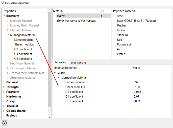
Click Apply.
Close the Materials management window.
2. Set material to include.
On the command panel, select (Mode — Material, Entity — Materials Management).
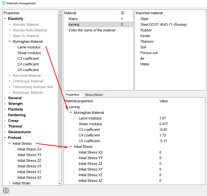
In the column Material enter the name of the material turning.
In the Material Properties column, select the created material, and then drag the desired properties to it from the left column.
Drag properties and specify their value:
Lame modulus: 1.07;
Shear modulus: 0.477;
C3 coefficient: -0.93;
C4 coefficient: 1.72;
C5 coefficient: -5.31;
Initial Stress ХХ: 0;
Initial Stress YY: 0;
Initial Stress ZZ: 0;
Initial Stress ХY: 0;
Initial Stress YZ: 0;
Initial Stress ХZ: 0.
Click Apply. Close the materials window.
3. Create a block for the plate.
On the command bar, select the block management module (Mode — Blocks, Entity – Block, Action – Add).

Block ID: 1;
Block Name: Matrix;
Entity List: Surface;
Entity ID(s): 9.
Click Apply.
4. Create a block to include.
On the command bar, select the block management module (Mode — Blocks, Entity – Block, Action – Add).
Block ID: 2;
Block Name: turning;
Entity List: Surface;
Entity ID(s): 11.
Click Apply.
5. Set the parameters of the first block.
On the command bar, select the block management module (Mode - Blocks, Entity - Block, Action - Block properties/parameters).

Set the following parameters:
Block ID(s): 1;
Category: Plane;
Material: Matrix;
Coordinate System: Global Cartesian;
Order: 2.
Click Apply.
6. Set the parameters of the second block.
On the command bar, select the block management module (Mode - Blocks, Entity - Block, Action - Block properties/parameters).
Set the following parameters:
Block ID(s): 2;
Material: turning;
Coordinate System: Global Cartesian;
Category: Plane;
Order: 2.
Click Apply.
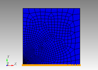
1. Fix the model in Y.
On the command panel, select the boundary conditions module (Mode — Boundary Conditions, Entity — Displacement, Action — Create).

Set the following parameters:
Entity List: Curve;
Entity ID(s): 30 24;
Degrees of Freedom: Y.
Click Apply.
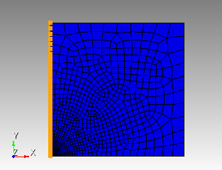
2. Fix the model in Х.
On the command panel, select the boundary conditions module (Mode — Boundary Conditions, Entity — Displacement, Action — Create).
Set the following parameters:
Entity List: Curve;
Entity ID(s): 32 7;
Degrees of Freedom: Х.
Click Apply.
3. Apply pressure to the edge of the plate
On the command panel, select the boundary conditions module (Mode — Boundary Conditions, Entity — Pressure, Action — Create).
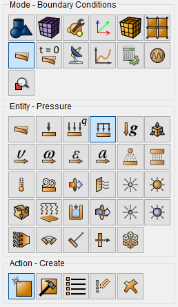
Set the following parameters:
Entity List: Curve;
Entity ID(s): 25;
Value: {-0.05*0.063}.
Click Apply.
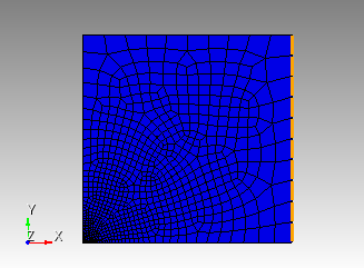
1. Set the type of problem you want to solve.
On the command bar, select the calculation settings module (Mode — Calculation Settings, Calculation Settings — Static, Static — General).

Please select:
Dimension: 2D;
Plane State: Plane Strain;
Model: Elasticity;
Set static Load Steps Count;
Load Steps Count: 2.
Click  to set the settings for the loading steps:
Click on the block name turning;
Set the active steps for the selected block: 2;
Set step materials;
Select material: turning.
Click Apply.
Click Start Calculation.
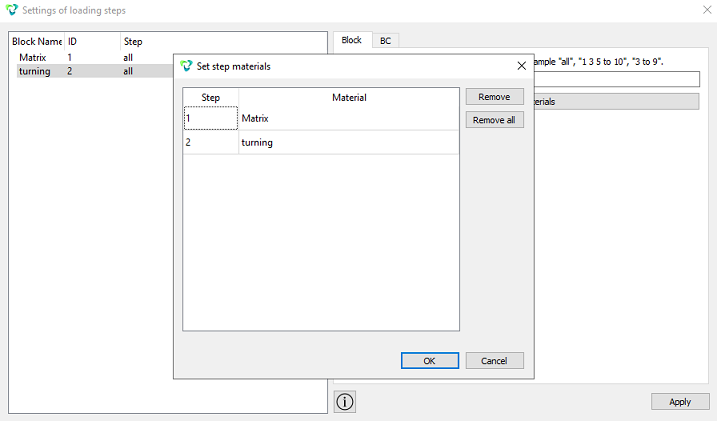
2. In a pop-up window select a folder to save the result and enter the file name.
3. In the case of a successful calculation, the console displays the message: Calculation finished successfully at "date" "time".
1. Open the file with the results. There are three ways to do that.
Click Ctrl+E.
From the main menu, select Calculation. Click Open Results.
Select Results on Command Panel (Mode - Results). Click Open results.

The FidesysViewer window will appear, in which you can view the calculation results.
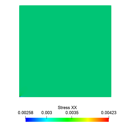
2. On the top panel, select the data of the calculation result to display. From the first dropdown list select Strees, from the second – XX.
Geometry creating, meshing, setting boundary conditions and materials can be performed using the console interface. Below is a link to the program code that allows you to perform the steps described above manual, you only need to specify the full path and name.