Search the documentation
Enter at least 2 characters
Enter at least 2 characters
 |
CAE Fidesys 9.0 Documentation |
1. Create a straight line.
On the command bar, select the module for constructing geometry (Mode — Geometry, Entity— Curve, Action — Create).
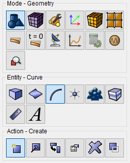
Select Line in the list of geometric elements.
Create it using Locations.
Set the following parameters:
Location: 0 0 0;
Location: 1 0 0.
Click Apply.
1. On the command bar, select the mesh module (Mode — Mesh, Entity — Curve, Action — Mesh).

Specify the parameters of mesh refinement:
Select Curves: all;
Settings For Curve: Equal;
Select the meshing parameters: Auto Size;
Auto Factor 3.
Click Apply Size.
Click Mesh.
In the command bar, select the module for specifying material properties (Mode — Material, Entity — Material Management).

Drag "Steel" from the "Imported Material" column to the "Material" window.
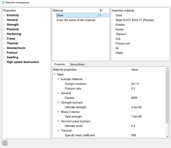
Click Apply.
Close the Material management window.
2. Create the block of one type of the material.
On the command bar, select the block management module (Mode - Blocks, Entity - Block, Action - Add).

Set the following parameters:
Block ID: 1;
Entity List: Curve;
Entity ID(s): 1 (or by the command all).
Click Apply.
3. Set block parameters.
On the command bar, select the block management module (Mode - Blocks, Entity - Block, Action - Block properties/parameters).

Set the following parameters:
Block ID(s): 1;
Category: Beam;
Material: Steel;
Coordinate System: Global Cartesian;
Order: 1.
Set the properties of the beam, to do this, click on the button  . From the Section profile drop-down list, select I-beam.
Set the following parameters:
Height (H): 0.1;
Bottom Width (B1): 0.055;
Top Width (B2): 0.055;
Top Thickness (c1): 0.0072;
Top Thickness (c2): 0.0072;
Thickness (d): 0.0045.
Click Apply.
Close the Set Beam Properties window.
Click Apply.
1.Fix the vertex 2 at all directions.
On the command panel, select the boundary conditions module (Mode — Boundary Conditions, Entity — Displacement, Action — Create).

Set the following parameters:
Entity List: Vertex;
Entity ID(s): 2;
Degrees of Freedom: Fix All.
Click Apply.
2. Set the velocity.
On the command panel, select the boundary conditions module (Mode - Boundary Conditions, Entity - Velocity, Action - Create).
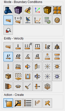
Set the following parameters:
Entity List: Vertex;
Entity ID(s): 1;
Degrees of Freedom: Y.
Click Apply.
1. Specify the type of problem you want to solve.
On the command bar, select the calculation settings module (Mode - Calculation Settings, Calculation Settings - Transient Analysis, Transient - General).
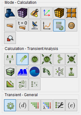
Set the solver settings:
Dimension: 3D;
Method: Full Solution;
Scheme: Implicit;
Max Time: 2;
Steps Count: 4;
Tick the box: Set Implicit Scheme Options;
Newmark Algorithm Gamma: 0.005.
Click Apply.
Click Start Calculation.
2. In a pop-up window select a folder to save the result and enter the file name.
3. In the case of a successful calculation, the console displays the message: Calculation finished successfully at "date" "time".
1. Open the file with the results. There are three ways to do it.
Click Ctrl+E.
Select Calculation → Open Results in the Main Menu. Click Open last result.
On the command panel, select the calculation settings module (Mode — Results). Click Open Results.

The FidesysViewer window will appear, in which you can view the calculation results.
On the top panel, select the calculation result data to display. From the first drop-down list select Displacements, from the second - Magnitude.

Connect the Warp By Vector filter (Menu - Alphabetical - Warp by Vector). Or use the corresponding button on the command panel:

In the Step window set 0 - the initial view of the model.
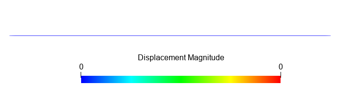
t=0
By switching steps from 0.5 to 2, you can view the deformed view of the model at all steps.
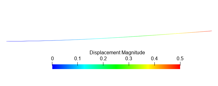
t=1
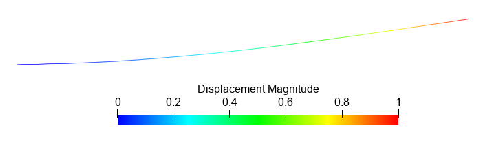
t=1.5
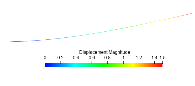
t=0.5
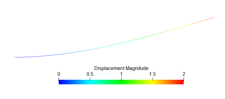
t=2
Geometry creating, meshing, setting boundary conditions and materials can be performed using the console interface. Below is a link to the program code that allows you to perform the steps described above manual, you only need to specify the full path and name.