Search the documentation
Enter at least 2 characters
Enter at least 2 characters
 |
CAE Fidesys 9.0 Documentation |
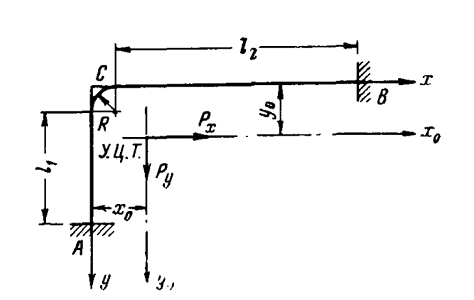
The calculation of the L-shaped pipeline section with an angle of rotation of 90 ° is carried out. Solution of the problem in the shell formulation using spectral shell elements. The considered impact on the pipeline is a temperature difference equal to 40 degrees.
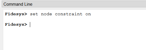
1. Enter the command for the node constraint building.
At the command line, type set node constraint on.
Click Enter.
2. Create a vertex.
On the command bar, select the module for constructing geometry (Mode - Geometry, Entity - Vertex, Action - Create).
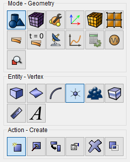
From the list of geometric primitives, select Location.
Set vertex coordinates:
Location...: 0 0 0.
Click Apply.
3. Create a vertex.
On the command bar, select the module for constructing geometry (Mode - Geometry, Entity - Vertex, Action - Create).
From the list of geometric primitives, select Location.
Set vertex coordinates:
Location...: 0 15 0.
Click Apply.
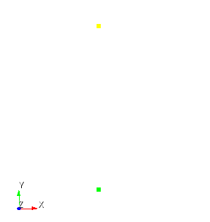
4. Create a vertex.
On the command bar, select the module for constructing geometry (Mode - Geometry, Entity - Vertex, Action - Create).
From the list of geometric primitives, select Location.
Set vertex coordinates:
Location...: 5 20 0.
Click Apply.
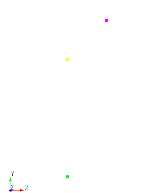
5. Create a vertex.
On the command bar, select the module for constructing geometry (Mode - Geometry, Entity - Vertex, Action - Create).
From the list of geometric primitives, select Location.
Set vertex coordinates:
Location...: 40 20 0.
Click Apply.
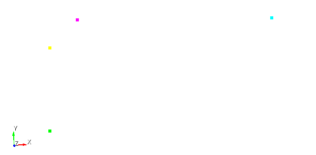
6. Create a curve connecting consecutive two vertices.
On the command bar, select the module for constructing geometry (Mode - Geometry, Entity - Curve, Action - Create).
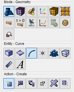
From the list of geometric primitives, select Line.
Set the following parameters:
Build Using: Vertex IDs;
Vertex IDs: 1 2.
Click Apply.

7. Create a curve connecting the vertices on the pipe bend.
On the command bar, select the module for constructing geometry (Mode - Geometry, Entity - Curve, Action - Create).
From the list of geometric primitives, select Arc Or Circle.
Set the following parameters:
Build Using:Vertices and Radius;
Start Vertex ID: 2;
End Vertex ID: 3;
Radius: 5;
Normal: 0 0 -1.
Click Apply.
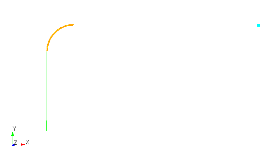
8. Create a curve connecting consecutive two vertices.
On the command bar, select the module for constructing geometry (Mode - Geometry, Entity - Curve, Action - Create).
From the list of geometric primitives, select Line.
Set the following parameters:
Build Using: Vertex IDs;
Vertex IDs: 3 4.
Click Apply.
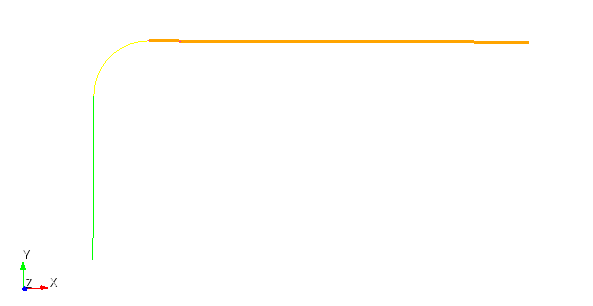
9. Combine curves.
On the command bar, select the module for constructing geometry (Mode - Geometry, Entity - Curve, Action - Create).
From the list of geometric primitives, select Combine.
Set the following parameters:
Curve ID(s): all;
Check the Delete Internal Vertices box.
Click Apply.
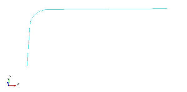
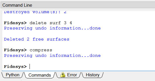
10. To eliminate gaps when deleting geometric objects, use compress command.
At the command line, type compress.
Click Enter.
11. Create a round surface.
On the command bar, select the module for constructing surface geometry (Mode - Geometry, Entity - Surface, Action - Create).

From the drop-down list, select Circle.
Set the following parameters:
Specify Circle Using: Radius;
Radius: 0.504.
YPlane.
Click Apply.
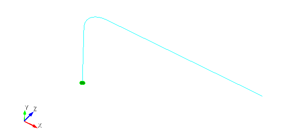
12. Create a surface along the entire curve.
On the command bar, select the module for constructing volume geometry (Mode - Geometry, Entity - Volume, Action - Create).

From the drop-down list, select Sweep.
Set the following parameters:
Surface ID(s): 1;
Sweep method: Along Curve;
Curve ID(s): 1.
Click Apply.
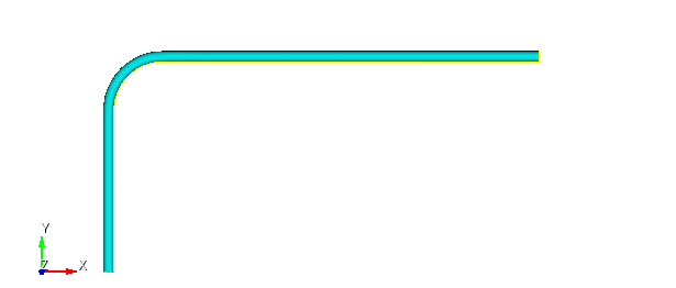
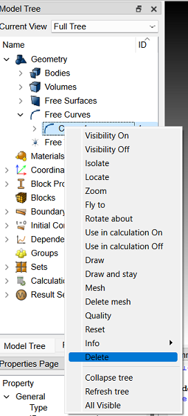
13. Delete the extra curve.
In the Model Tree, select (Geometry, Free Curves, Curve 1).
Right click on and select Delete.
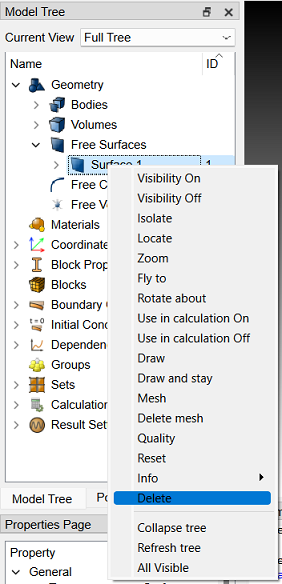
14. Remove excess surface.
In the Model Tree, select (Geometry, Free Surfaces, Surface 1).
Right click on and select Delete.
15. Remove excess volume.
On the command bar, select the module for constructing volume geometry (Mode - Geometry, Entity - Volume, Action - Delete).
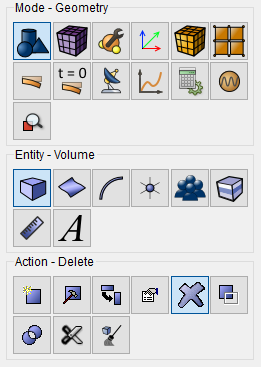
Set the following parameters:
Volume ID(s): 2.
Check the box Keep Lower Geometry.
Click Apply.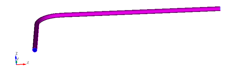
16. Remove excess surfaces.
On the command bar, select the module for constructing surface geometry (Mode - Geometry, Entity - Surface, Action - Delete).
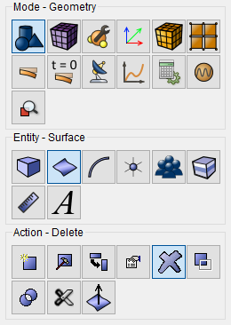
Set the following parameters:
SurfaceID(s): 3 4.
Click Apply.
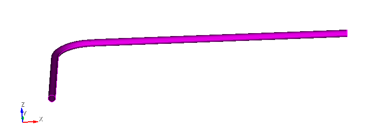
17. To eliminate gaps while deleting geometric objects, use compress command.
At the command line, type compress.
Click Enter.
18. Cut the piping model in two at the bend.
On the command bar, select the module for constructing volume geometry (Mode - Geometry, Entity - Volume, Action - Webcat).
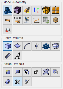
From the drop-down list, select Coordinate Plane.
Set the following parameters:
Volume ID(s): all;
Plane: ZX;
Offset Value: 20.
Check the Rotate Plane box.
Angle: -45;
Direction: Z Axis.
Click Apply. 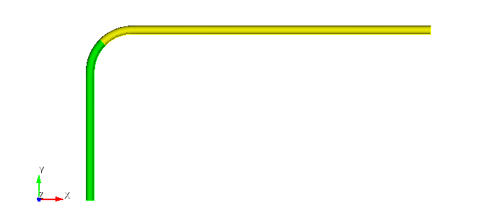
19. Merge curves.
On the command bar, select the module for constructing geometry (Mode - Geometry, Entity - Curve, Action - Merge).
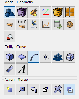
From the drop-down list, select Merge.
Set the following parameters:
Curve ID(s): all.
Click Apply.
1. Condition the pipeline mesh.
On the command bar, select the surface mesh module (Mode — Mesh, Entity – Surface, Action – Intervals).
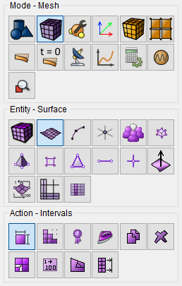
From the drop-down list, select: Geometry Adaptive.
Select Surfaces: all.
Click Apply Size.
Click Mesh.
2. Refine the mesh.
On the command bar, select the surface mesh module (Mode - Mesh, Entity - Surface, Action - Refine).
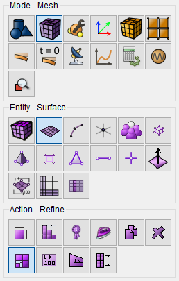
From the drop-down list, select: General Refinement.
Surface ID(s): all.
Click Apply.
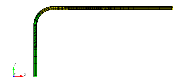
1. Create the material.
In the command bar, select the module for specifying material properties (Mode - Material, Entity - Materials Management).

From the right column, drag the material Steel into the column Material.
In the material properties, find Young's modulus and change its value to 2.1e+11.
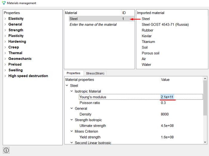
Click Apply.
Close the Materials management window.
2. Create the first block for the parallelepiped.
On the command bar, select the block management module (Mode — Blocks, Entity - Block, Action - Add).

Set the following parameters:
Entity List: Surface;
Entity ID(s): all.
Click Apply.
3. Set the parameters for the blocks.
On the command bar, select the block management module (Mode - Blocks, Entity - Block, Action - Block properties/parameters).

Set the following parameters:
Block ID(s): 1;
Category: Shell;
Coordinate System: Global Cartesian;
Order: 1.
Set shell properties, to do this, click on the button  .
.
Set the following parameters:
Thickness: 0.012;
Material: Steel;
Angle: 0.
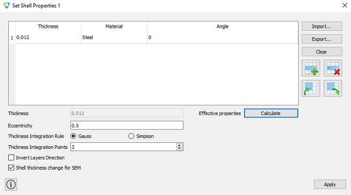
Click Apply.
Close Shell Properties.
Click Apply.
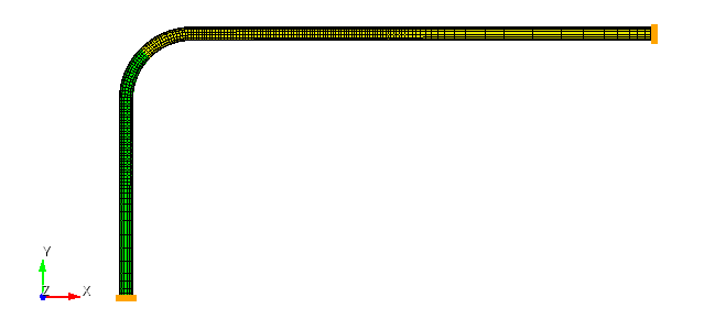
1. Fix the lines at the ends of the pipeline in all degrees of freedom.
On the command panel, select the boundary conditions module (Mode - Boundary Conditions, Entity - Displacement, Action — Create).

Set the following parameters:
Entity List: Curve;
Entity ID(s): 1 3;
Degrees of Freedom: Fix All.
Click Apply.
2. Set the thermal effect.
On the command panel, select the boundary conditions module (Mode - Boundary Conditions, Entity - Temperature, Action — Create).
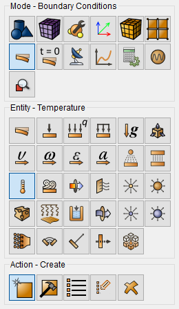
Set the following parameters:
Entity List: Surface;
Entity ID(s): all;
Value: 40.
Click Apply.
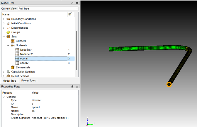
1. To simplify the display of reactions in pins, let’s create sets nodes with fixed curves.
Secure the first curve. On the command bar, select the set module nodes (Mode - Sets, Entity - Nodeset, Action — Create nodeset).
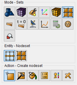
Set the following parameters:
Nodeset ID: 3;
Nodeset Name: opora1;
Select: Curve;
ID(s): 1.
Click Apply.
2. Fasten the second curve.
Set the following parameters:
Nodeset ID: 4;
Nodeset Name: opora2;
Select: Curve;
ID(s): 3.
Click Apply.
1. Set the type of problem you want to solve.
On the command bar, select the calculation settings module (Mode - Calculation Settings, Calculation Settings — Static, Static — General).

Select:
Dimension: 3D;
Model: Elasticity.
Click Apply.
2. Specify the settings for the output fields of the task.
On the command bar, select the calculation settings module (Mode - Calculation Settings, Calculation Settings — Static, Static — Output Fields).
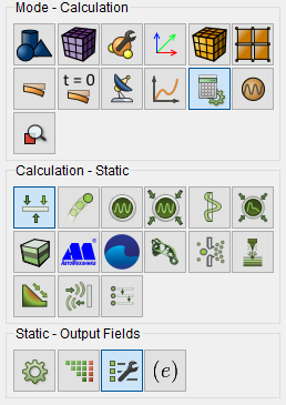
Select:
Check the box: Nodal and Reaction Forces.
Click Apply.
Click Start Calculation.
3. In the window that appears, select the directory where the result will be saved.
4. In the case of a successful calculation, the console displays the message: Calculation finished successfully at "date" "time".
1. Open the file with the results. There are three ways to do that.
Click Ctrl+E.
From the main menu, select Calculation. Click Open Results.
Select Results on Command Panel (Mode - Results). Click Open results.

A window will appear FidesysViewer, in which you can read with the results of the calculation.
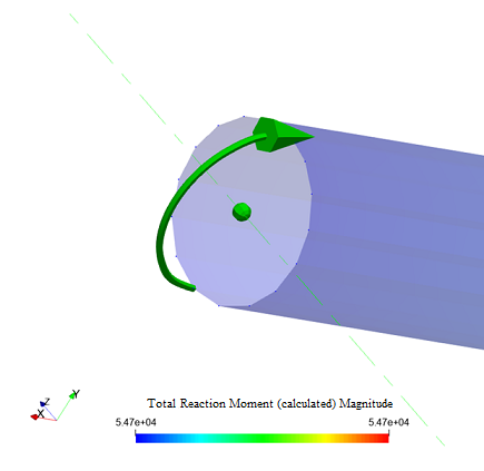
2. Determine the total reaction moment at the end of the pipeline in the support 1.
On the top toolbar, select Filters - Alphabetical – Total Force and Moment.
On the properties tab, select:
Nodes Selection: With Node Set.
Node Set: opora1;
Center Origin Mode: Center Of Reaction.
Click Apply.
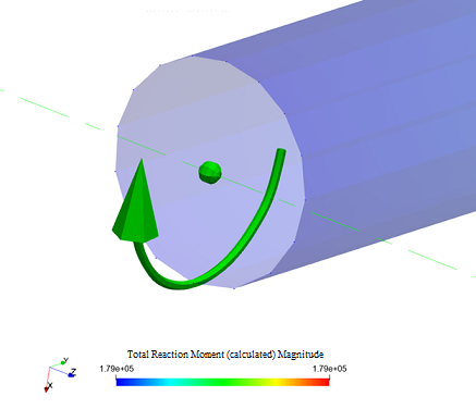
3. Similarly, enter the total moment of reaction for the second support.
On the properties tab, select:
Nodes Selection: With Node Set.
Node Set: opora2;
Center Origin Mode: Center Of Reaction.
Click Apply.
Geometry creating, meshing, setting boundary conditions and materials can be performed using the console interface. Below is a link to the program code that allows you to perform the steps described above manual, you only need to specify the full path and name.