Search the documentation
Enter at least 2 characters
Enter at least 2 characters
 |
CAE Fidesys 9.0 Documentation |
For modal analysis, the ability to calculate models, some of the elements of which have zero density and play the role of stiffening elements, and the mass is "point mass" elements. This functionality allows you to perform calculations for models in a simplified setting - when complex structures (usually on preliminary design stages) are greatly simplified for the fastest possible results.
*Note: When setting zero density, the number of output frequencies will be exactly as many as there is enough data on the masses, while you can set any number in the calculation.
1. Create a curve.
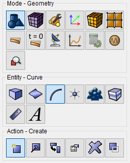
On the command bar, select the module for constructing geometry (Mode — Geometry, Entity — Curve, Action — Create).
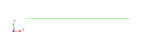
Select Location Based from the list of geometric primitives.
Set the following parameters:
Location: 0 0 0;
Location: 1 0 0.
Click Apply.
1. Condition the pipeline mesh.
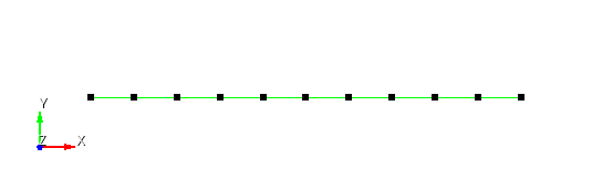
On the command bar, select the mesh module (Mode — Mesh, Entity — Curve, Action — Mesh).

Specify the required curves:
Select Curves: 1;
Settings For Curve: Equal;
Interval;
Interval: 10.
Click Apply Size.
Click Mesh.
1.Set the material.
In the command bar, select the module for specifying material properties (Mode — Material, Entity — Material Management).

In the "Material" column, enter the material name material1.
Click Apply.
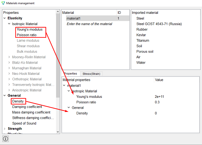
In the Material Properties column, select the created material, then drag to him the desired properties from the left column.
Drag properties and specify their value:
Young's modulus: 2e+11;
Poisson ratio: 0.3;
Density: 0.
Click Apply.
Close the Materials management window.
2. Create a block for the curve.
On the command bar, select the block management module (Mode — Blocks, Entity – Block, Action – Add).

Set the following options:
Block ID: 1;
Entity List: Curve;
Entity ID(s): 1.
Click Apply.
3. Create a block for the vertex.
On the command bar, select the block management module (Mode — Blocks, Entity – Block, Action – Add).
Set the following options:
Block ID: 2;
Entity List: Vertex;
Entity ID(s): 2.
Click Apply.
4. Set the block 1 parameters.
On the command bar, select the block management module (Mode - Blocks, Entity - Block, Action - Block properties/parameters).

Set the following options:
Block ID(s): 1;
Category: Beam;
Material: material1;
Coordinate System: Global Cartesian;
Order: 1.
Set the properties of the beam, to do this, click on the button  . From the Section profile drop-down list, select Rectangle.
Set the following parameters:
Height: 0.01;
Width: 0.01.
Click Apply.
Close the Set Beam Properties window.
Click Apply.
5. Set the block 2 parameters.
On the command bar, select the block management module (Mode - Blocks, Entity - Block, Action - Block properties/parameters).
Set the following options:
Block ID(s): 2;
Category: Lumped Mass;
Coordinate System: Global Cartesian;
Block Properties ID: 1.
Set the properties of the lumped mass, to do this, click on the button
.
Set the following parameters:
Set Masses: Mass;
Mass: 100.
Click Apply.
Close the Set Lumped Mass Properties window.
Click Apply.
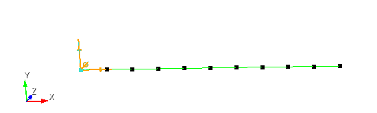
1. Fix the beam at the top.
On the command panel, select the boundary conditions module (Mode — Boundary Conditions, Entity — Displacement, Action — Create ).

Set the following parameters:
Entity List: Vertex;
Entity ID(s): 1;
Degrees of Freedom: Fix All.
Click Apply.
1. Set the type of problem you want to solve.
On the command bar, select the calculation settings module (Mode — Calculation Settings, Calculation Settings — Frequency Analysis, Frequency Analysis — General).
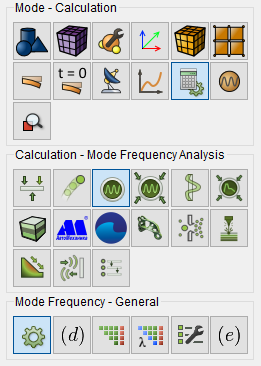
Please select:
Dimension: 3D;
Number of Eigenmodes: 3.
Click Apply.
Click Start Calculation.
2. In a pop-up window select a folder to save the result and enter the file name.
3. In the case of a successful calculation, the console displays the message: Calculation finished successfully at "date" "time".
1. Open the file with the results. There are three ways to do that.
Click Ctrl+E.
From the main menu, select Calculation. Click Open Results.
Select Results on Command Panel (Mode - Results). Click Open results.

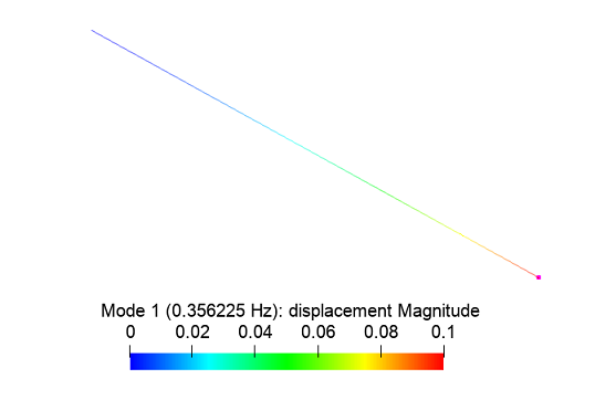
The Fidesys Viewer window will appear in which you can view with the calculation results.
For geometry generation, meshing, setting boundary conditions and materials you can use Console Interface. The following program code allows performing the steps of the above-described guide, you only need to manually specify the full path and name of the file to be saved.