Search the documentation
Enter at least 2 characters
Enter at least 2 characters
 |
CAE Fidesys 9.0 Documentation |
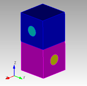
The problem of determining the effective mechanical characteristics is considered. for orthogonally reinforced composite. Orthogonally reinforced is called composite, in which one fiber directed along the Y axis accounts for k fibers directed along the X axis.
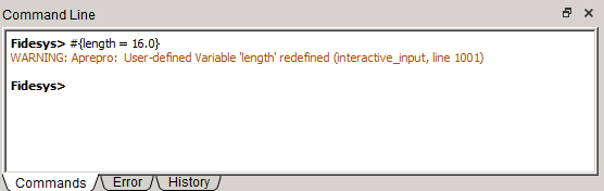
1. Enter length constant.
On the command line, enter a length constant of 16.
After entering the command #{length = 16.0} click Enter.
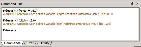
2. Enter width constant.
On the command line, enter a width constant of 16.
After entering the command #{pitch = 16.0} click Enter.
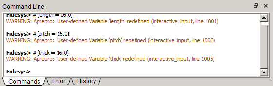
3. Enter the height constant.
On the command line, enter a height constant of 16.
After entering the command #{thick = 16.0} click Enter.
4. Enter thread constant.
On the command line, enter a thread constant equal to 10.
After entering the command #{conc = 10.0} click Enter.
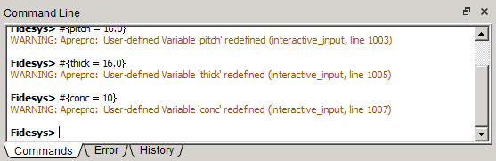
5. Enter the command to calculate the thread radius constant.
On the command line, enter the thread radius constant.
After entering the command #{rad = sqrt( 0.01 * pitch * thick * conc / 3.1415926 )} click Enter.
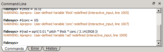
6. Enter the size of the mesh.
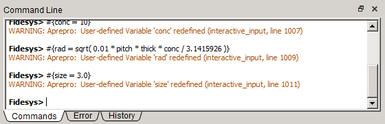
In the command line, enter a grid size value equal to 3.
After entering the command #{size = 3.0} click Enter.
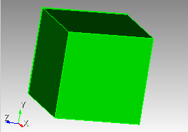
1. Create a parallelepiped.
On the command bar, select the module for constructing volume geometry (Mode - Geometry, Entity - Volume, Action - Create).

From the list of geometric primitives, select Brick.
Set the following parameters:
X (width): {length};
Y (heigtht): {pitch};
Z (depth): {thick}.
Click Apply.
2. Create a cylinder.
On the command bar, select the module for constructing volume geometry (Mode - Geometry, Entity - Volume, Action - Create).
From the list of geometric primitives, select Cylinder.
Set the following parameters:
Heigtht: {length};
Circular;
Radius: {rad}.
Click Apply.
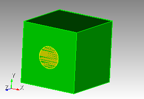
3. Rotate the cylinder.
On the command bar, select the module for constructing volume geometry (Mode - Geometry, Entity - Volume, Action - Transform).
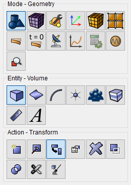
From the list, select Rotate.
Set the following parameters:
Volume ID(s): 2;
Include Merged;
Angle: 90;
Rotate About: Y-Axis.
Click Apply.
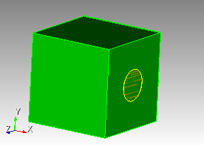
4. Subtract the volume of the cylinder.
On the command bar, select the module for constructing volume geometry (Mode - Geometry, Entity — Volume, Action — Boolean).
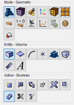
From the list, select Subtract.
Set the following parameters:
Volume ID(s): 1;
Volume ID(s): 2.
Click Apply.
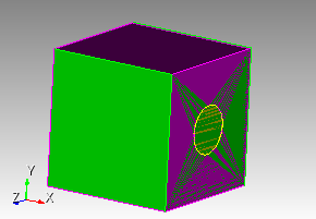
5. Delete volume.
On the command bar, select the module for constructing volume geometry (Mode - Geometry, Entity — Volume, Action — Delete).
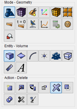
Set the following parameters:
Volume ID(s): 1.
Click Apply.
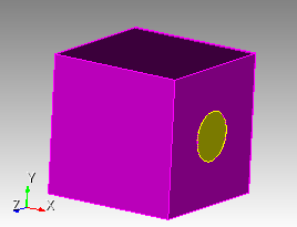
1. Move the created model.
On the command bar, select the module for constructing volume geometry (Mode - Geometry, Entity - Volume, Action - Transform).
From the list, select Move.
Set the following parameters:
Volume ID(s): all;
Include Merged;
Select Method: Distance;
Z Distance: {-thick/2.0}.
Click Apply.
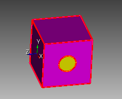
2. Move the generated model using copying geometry.
Enter a command at the command line to move the geometry. In this case, the original model remains in place.
Enter volume all move z {thick} copy.
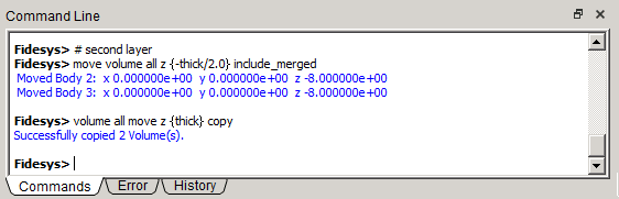
Click Enter.
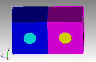
3. Rotate volumes 2 and 3 by 90°.
On the command bar, select the module for constructing volume geometry (Mode - Geometry, Entity - Volume, Action - Transform).
From the list, select Rotate.
Set the following parameters:
Volume ID(s): 2 3;
Include Merged;
Angle: 90;
Rotate About: Z-Axis.
Click Apply.
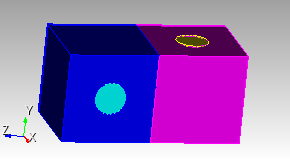
4. Print and merge geometric volumes.
On the command bar, select the module for constructing volume geometry (Mode - Geometry, Entity - Volume, Action — Imprint and Merge).
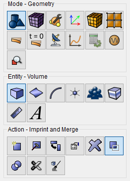
From the list, select Imprint/Merge Volumes.
Set the following parameters:
Volume ID(s): all.
Click Apply.
1. Create a tetrahedral mesh for the entire model.
On the command bar, select the volume mesh module (Mode — Mesh, Entity – Volume, Action – Mesh).
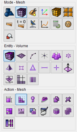
From the list, select Tetmesh.
Select Volumes: all.
Click Mesh.
2. Create a mesh.
On the command bar, select the volume mesh module (Mode — Mesh, Entity – Volume, Action – Intervals).
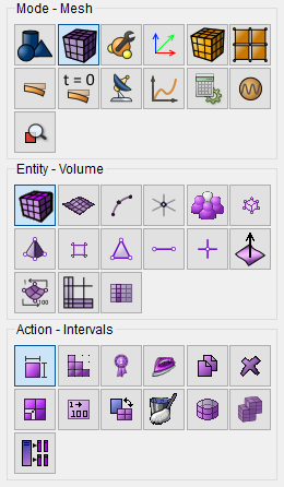
Select from the list Approximate Size.
Set the following parameters:
Select Volumes: all;
Approximate Size: {size}.
Click Apply Size.
Click Mesh.
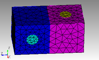
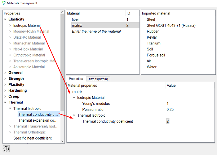
1. Set the first material.
In the command bar, select the module for specifying material properties (Mode — Material, Entity — Materials Management).

In the column Material enter the name of the material fiber.
Click Apply.
In the column Material properties select the created material, then drag the desired properties to it from the left column.
Drag properties and specify their value:
Young's modulus: 1;
Poisson ratio: 0.25;
Thermal conductivity coefficient: 10.
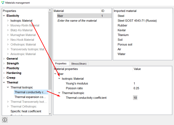
Click Apply.
Close the Materials management window.
Set the second material.
In the column Material enter the name of the material matrix.
Click Apply.
In the column Material properties select the created material, then drag the desired properties to it from the left column.
Drag properties and specify their value:
Young's modulus: 1;
Poisson ratio: 0.25;
Thermal conductivity coefficient: 2.
Click Apply.
2. Create the first block for two cylinders.
On the command bar, select the block management module (Mode — Blocks, Entity – Block, Action – Add).

Set the following parameters:
Entity List: Volume;
Entity ID(s): 2 4.
Click Apply.
3. Create a second block for two bricks.
On the command bar, select the block management module (Mode — Blocks, Entity – Block, Action – Add).
Set the following parameters:
Entity List: Volume;
Entity ID(s): 3 5.
Click Apply.
4. Set parameters for the first block.
On the command bar, select the block management module (Mode - Blocks, Entity - Block, Action - Block properties/parameters).

Set the following parameters:
Block ID(s): 1;
Category: Solid;
Material: fiber;
Coordinate System: Global Cartesian;
Order: 2.
Click Apply.
5. Set parameters for the second block.
On the command bar, select the block management module (Mode - Blocks, Entity - Block, Action - Block properties/parameters).
Set the following parameters:
Block ID(s): 1;
Category: Solid;
Material: matrix;
Coordinate System: Global Cartesian;
Order: 2.
Click Apply.
1. Set the type of problem you want to solve.
On the command bar, select the calculation settings module (Mode — Calculation Settings, Calculation Settings — Effective Properties, Effective Properties — General).
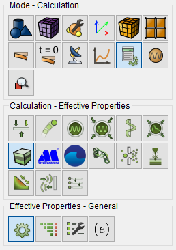
Please select:
Dimension: 3D;
Type of BC: Nonperiodic;
Model: Elasticity.
Click Apply.
Click Start Calculation.
2. In a pop-up window select a folder to save the result and enter the file name.
3. If the calculation is finished successfully, you will see a message in the Console: “Calculation finished successfully at "date time".
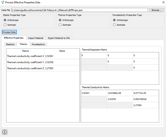
1. Check out the results in the window that appears Process effective properties data.
Desired results are shown diagonally:
Geometry creating, meshing, setting boundary conditions and materials can be performed using the console interface. Below is a link to the program code that allows you to perform the steps described above manual, you only need to specify the full path and name.