Search the documentation
Enter at least 2 characters
Enter at least 2 characters
 |
CAE Fidesys 9.0 Documentation |
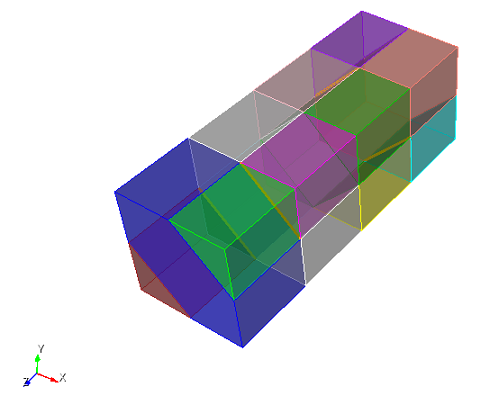
1. Create a brick.
On the command bar, select the module for constructing volume geometry (Mode - Geometry, Entity - Volume, Action - Create).

From the list of geometric primitives, select Brick.
Set the following parameters:
X (width): 11.3137085;
Y (height): 11.3137085;
Z (depth): 32.
Click Apply.
2. Cut the volume.
On the command bar, select the module for constructing volume geometry (Mode - Geometry, Entity - Volume, Action — Webcut).
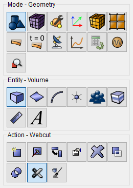
From the list of possible types of sections, select Coordinate Plane.
Set the following parameters:
Volume ID(s): 1;
Cut Plane: XY;
Offset Value: 0;
Merge.
Click Apply.
3. Make a second incision.
On the command bar, select the module for constructing volume geometry (Mode - Geometry, Entity - Volume, Action — Webcut).
From the list of possible types of sections, select Coordinate Plane.
Set the following parameters:
Volume ID(s): 1;
Cut Plane: XY;
Offset Value: 8.
Click Apply.
4. Make a third incision.
On the command bar, select the module for constructing volume geometry (Mode - Geometry, Entity - Volume, Action — Webcut).
From the list of possible types of sections, select Coordinate Plane.
Set the following parameters:
Volume ID(s): 1;
Cut Plane: XY;
Offset Value: -8.
Click Apply.
5. Make the fourth incision.
On the command bar, select the module for constructing volume geometry (Mode - Geometry, Entity - Volume, Action — Webcut).
From the list of possible types of sections, select Coordinate Plane.
Set the following parameters:
Volume ID(s): 1 3;
Cut Plane: YZ;
Offset Value: 5.65685425;
Rotate Plane;
Angle: 45;
Direction: Z Axis.
Click Apply.
6. Make the fifth incision.
On the command bar, select the module for constructing volume geometry (Mode - Geometry, Entity - Volume, Action — Webcut).
From the list of possible types of sections, select Coordinate Plane.
Set the following parameters:
Volume ID(s): 5 6;
Cut Plane: YZ;
Offset Value: -5.65685425;
Rotate Plane;
Angle: 45;
Direction: Z Axis.
Click Apply.
7. Make the sixth incision.
On the command bar, select the module for constructing volume geometry (Mode - Geometry, Entity - Volume, Action — Webcut).
From the list of possible types of sections, select Coordinate Plane.
Set the following parameters:
Volume ID(s): 2 4;
Cut Plane: YZ;
Offset Value: 5.65685425;
Rotate Plane;
Angle: -45;
Direction: Z Axis.
Click Apply.
8. Make the seventh incision.
On the command bar, select the module for constructing volume geometry (Mode - Geometry, Entity - Volume, Action — Webcut).
From the list of possible types of sections, select Coordinate Plane.
Set the following parameters:
Volume ID(s): 9 10;
Cut Plane: YZ;
Offset Value: -5.65685425;
Rotate Plane;
Angle: -45;
Direction: Z Axis.
Click Apply.
9. Merge all the received volumes. Enter the following commands in the
command line:
imprint all
merge all
1. In the command line, write set default element tri.
2. On the command bar, select the volume mesh module (Mode - Mesh, Entity - Volume, Action - Intervals).
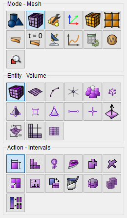
Set the following parameters:
Approximate Size;
Select Volumes: all;
Approximate Size: 3.
Click Apply Size.
Click Mesh.
In the command bar, select the module for specifying material properties (Mode - Material, Entity - Materials Management).

Create two materials.
1. fiber - Properties of the thread material:
Young's modulus E = 200000;
Poisson ratio v = 0.25.
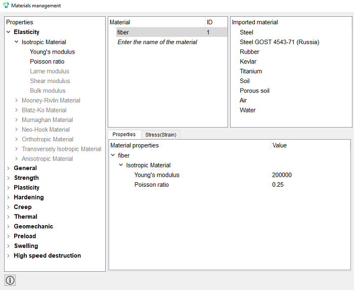
2. matrix - Properties of the matrix material:
Young's modulus E = 2;
Poisson ratio v = 0.49.
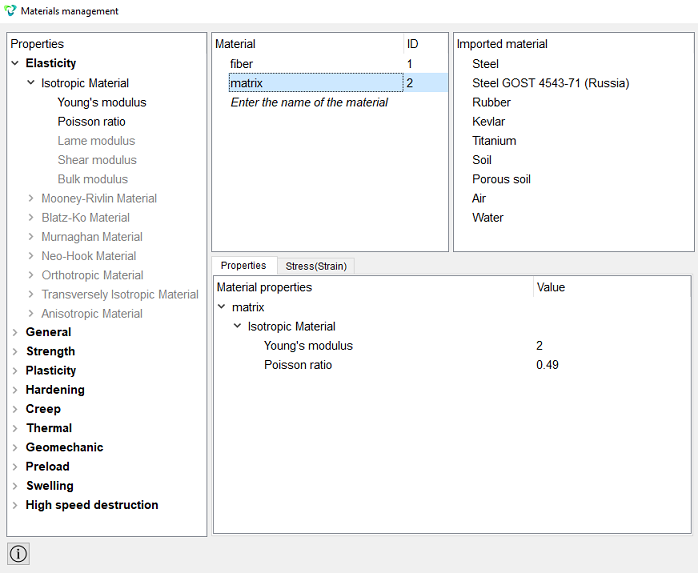
Click Apply.
Close the Materials management window.
1. Create the first block.
On the command bar, select the block management module (Mode - Blocks, Entity - Block, Action — Add).

Set the following parameters:
Entity List: Curve;
Entity ID(s): 61 93 125 157.
Click Apply.
2. Create a second block.
On the command bar, select the block management module (Mode - Blocks, Entity - Block, Action — Add).
Set the following parameters:
Entity List: Volume;
Entity ID(s): all.
Click Apply.
3. Set parameters for block №1.
On the command bar, select the block management module (Mode - Blocks, Entity - Block, Action — Block properties/parameters).

Set the following parameters:
Block ID(s): 1;
Category: Beam;
Material: fiber;
Coordinate System: Global Cartesian;
Order: 2.
Set the properties of the beam, to do this, click on the button  . From the Section profile drop-down list, select Ellipse.
Set the following parameters:
Minor Axis (b): 5;
Major Axis (a): 5.
Click Apply.
4. Set the parameters for block №2.
On the command bar, select the block management module (Mode - Blocks, Entity - Block, Action — Block properties/parameters).
Set the following parameters:
Block ID(s): 2;
Category: Solid;
Material: matrix;
Coordinate System: Global Cartesian;
Order: 2.
Click Apply.
1. Specify the type of task you want to solve.
On the command bar, select the calculation settings module (Mode - Calculation Settings, Calculation Settings — Effective Properties, Effective Properties - General).
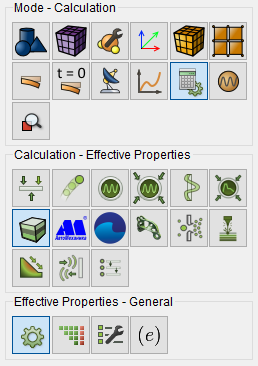
Select:
Dimensions: 3D;
Type of BC: Periodic;
Model: Elasticity.
Click Apply.
2. On the command bar, select the calculation settings module (Mode - Calculation Settings, Calculation Settings — Effective Properties, Effective Properties - Solver).
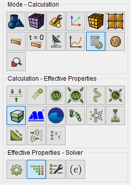
Select:
Method: Direct;
Use Uzawa iteration: No.
Click Apply.
3. Configure the output fields of the calculation results.
On the command bar, select the calculation settings module (Mode - Calculation Settings, Calculation settings — Effective Properties, Effective Properties — Output Fields).
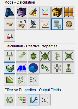
Select:
VTU File;
Log File.
Click Apply.
Click Start Calculation.
4. In the window that appears, select the directory where the result will
be saved and enter the file name.
5. In case of a successful calculation, the console will display the message: "Calculation finished successfully at "date"time".
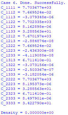
6. After the calculation is completed, the results will appear in the command line.
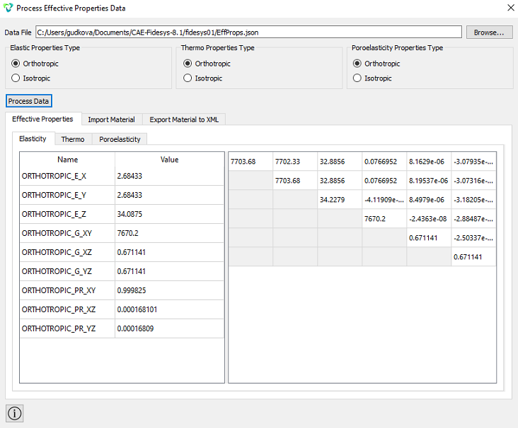
In the window that appears, select:
Type of elastic properties: Orthotropic;
Type of temperature properties: Orthotropic.
Click Process the data.
Geometry creating, meshing, setting boundary conditions and materials can be performed using the console interface. Below is a link to the program code that allows you to perform the steps described above manual, you only need to specify the full path and name.