Search the documentation
Enter at least 2 characters
Enter at least 2 characters
 |
CAE Fidesys 9.0 Documentation |
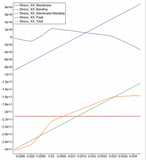
The mechanics of the process of setting the line and plotting linearized stresses. When choosing a reference line, the program determines the stress components along this line and additionally performs a linearization procedure on these components - allocation of membrane, bending and nonlinear stresses. By linearized components the sums of membrane and bending are determined.
A description of the linearization process can be studied in this section.
1. Create the first cylinder.
On the command bar, select the module for constructing volume geometry (Mode - Geometry, Entity - Volume, Action - Create).

Select Cylinder from the list of geometric primitives.
Set the following parameters:
Height: 0.8;
Section type: Circular;
Radius: 0.1.
Click Apply.
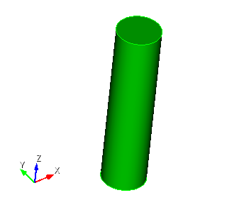
2. Create a second cylinder.
On the command bar, select the module for constructing volume geometry (Mode - Geometry, Entity - Volume, Action - Create).
Select Cylinder from the list of geometric primitives.
Set the following parameters:
Height: 0.8;
Section type: Circular;
Radius: 0.092.
Click Apply.
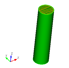
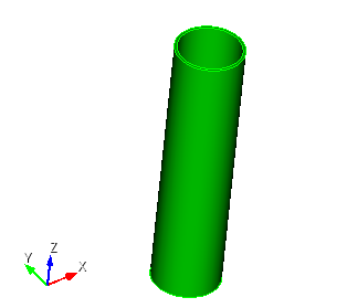
3. Subtract from the first cylinder the second.
On the command bar, select the module for constructing volume geometry (Mode - Geometry, Entity - Volume, Action — Boolean).
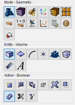
From the list of operations, select Subtract.
Set the following parameters:
A Volume ID(s): 1;
B Volume ID(s): 2.
Click Apply.
4. Create a third cylinder.
On the command bar, select the module for constructing volume geometry (Mode - Geometry, Entity - Volume, Action - Create).
Select Cylinder from the list of geometric primitives.
Set the following parameters:
Height: 0.8;
Section type: Circular;
Radius: 0.05.
Click Apply.
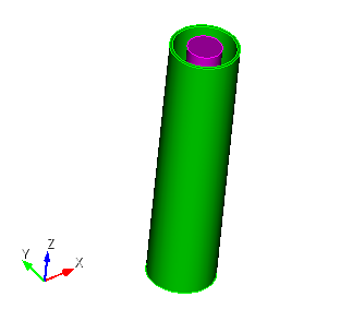
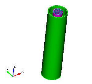
5. Create the fourth cylinder.
On the command bar, select the module for constructing volume geometry (Mode - Geometry, Entity - Volume, Action - Create).
Select Cylinder from the list of geometric primitives.
Set the following parameters:
Height: 0.8;
Section type: Circular;
Radius: 0.045.
Click Apply.
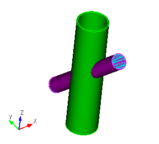
6. Rotate the cylinders.
On the command bar, select the module for constructing volume geometry (Mode - Geometry, Entity - Volume, Action — Transform).
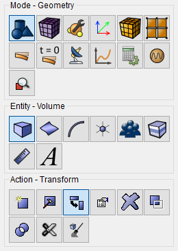
From the list of operations, select Rotate.
Set the following parameters:
Volume ID(s): 3 4;
Include Merged;
Angle: 45;
Rotate About: Х-Axis.
Click Apply.
7. Copy and reflect volumes.
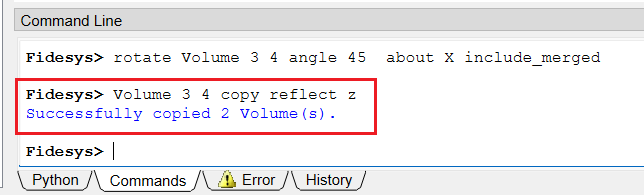
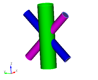
At the command line, type "Volume 3 4 copy reflect z".
The reflect command is applied when selecting (Mode - Geometry, Entity - Volume, Action — Transform) from the drop-down list Reflect.
But when adding the copy command, the volumes will also be copied.
Click Enter.
8. Copy surfaces.
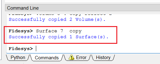
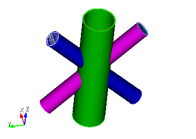
At the command line, type "Surface 7 copy".
Click Enter.
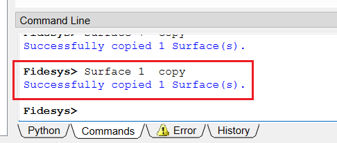
9. Copy surfaces.
At the command line, type "Surface 1 copy".
Click Enter.
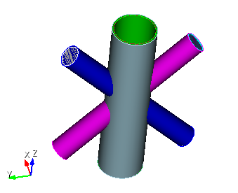
10. Cut the volume.
On the command bar, select the module for constructing volume geometry (Mode - Geometry, Entity - Volume, Action — Webcut).
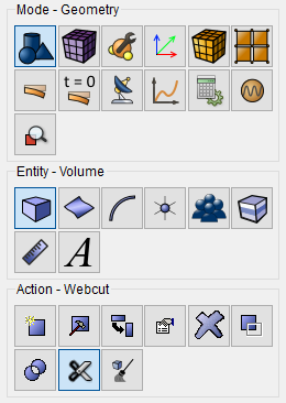
From the drop-down list, select Sheet.
Set the following parameters:
Volume ID(s): 3 4 5 6;
With Body ID: 7.
Click Apply.
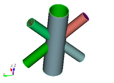
11. Delete volumes.
On the command bar, select the module for constructing volume geometry (Mode - Geometry, Entity - Volume, Action — Delete).
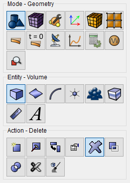
Set the following parameters:
Volume ID(s): 5 3 14 9.
Click Apply.
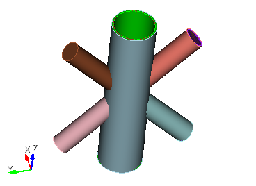
12. Delete volumes.
On the command bar, select the module for constructing volume geometry (Mode - Geometry, Entity - Volume, Action — Delete).
Set the following parameters:
Volume ID(s): 6 11.
Click Apply.
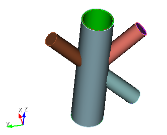
13. Delete volumes.
On the command bar, select the module for constructing volume geometry (Mode - Geometry, Entity - Volume, Action — Delete).
Set the following parameters:
Volume ID(s): 4 16.
Click Apply.
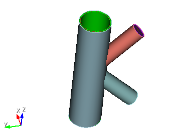
14. Subtract сylinder.
On the command bar, select the module for constructing volume geometry (Mode - Geometry, Entity - Volume, Action — Boolean).
From the list of operations, select Subtract.
Set the following parameters:
A Volume ID(s): 1 13;
B Volume ID(s): 15.
Click Apply.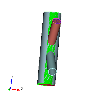
15. Subtract сylinder.
On the command bar, select the module for constructing volume geometry (Mode - Geometry, Entity - Volume, Action — Boolean).
From the list of operations, select Subtract.
Set the following parameters:
A Volume ID(s): 10 1;
B Volume ID(s): 12.
Click Apply.
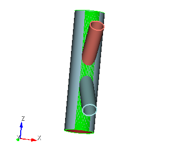
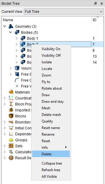
16. Delete the body inside the cylinder.
In the entity tree, select (Geometry — Bodies — Body 7). Right click on it and select Delete.
17. Cut the volume.
On the command bar, select the module for constructing volume geometry (Mode - Geometry, Entity - Volume, Action — Webcut).
From the drop-down list, select Sheet.
Set the following parameters:
Volume ID(s): 10 13;
With Body ID: 8.
Click Apply.
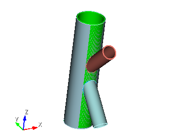
18. Delete volumes.
On the command bar, select the module for constructing volume geometry (Mode - Geometry, Entity - Volume, Action — Delete).
Set the following parameters:
Volume ID(s): 8.
Click Apply.
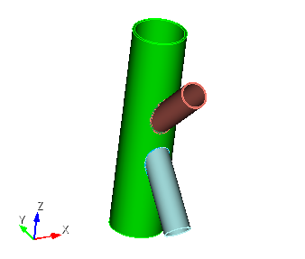
19. Unite volumes.
On the command bar, select the module for constructing volume geometry (Mode - Geometry, Entity - Volume, Action — Boolean).
From the list of operations, select Unite.
Set the following parameters:
Volume ID(s): 17 1.
Click Apply.
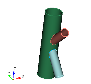
20. Unite volumes.
On the command bar, select the module for constructing volume geometry (Mode - Geometry, Entity - Volume, Action — Boolean).
From the list of operations, select Unite.
Set the following parameters:
Volume ID(s): 18 17.
Click Apply.
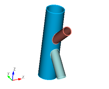
21. Imprint and merge volumes.
On the command bar, select the module for constructing volume geometry (Mode - Geometry, Entity - Volume, Action — Imprint and Merge).
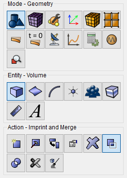
From the list of operations, select Imprint/Merge Volumes.
Set the following parameters:
Volume ID(s): all.
Click Apply.
1. Set Mesh Options
On the command bar, select the volume mesh module (Mode - Mesh, Entity - Volume, Action - Mesh).
From the list of actions, select Tetmesh.
Set the following parameters:
Select Volumes: all.
Click Apply Scheme.
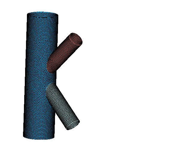
2. Create a mesh.
On the command bar, select the volume mesh module (Mode - Mesh, Entity - Volume, Action - Intervals).
From the list of actions, select Automatic Sizing.
Set the following parameters:
Select Volumes: all;
Auto Factor: 4.
Click Apply Size.
Click Mesh.
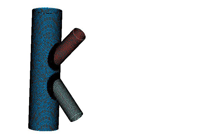
3. Refine the mesh on the curve.
On the command bar, select the volume mesh module (Mode - Mesh, Entity - Volume, Action - Refine).
From the list of actions, select General Refinement.
Set the following parameters:
Curve ID(s): 47 43;
Split Iterations: 2;
Bias: 1.0;
Element Depth: 3.
Click Apply.
1. Specify the material.
In the command bar, select the module for specifying material properties (Mode — Material, Entity — Materials Management).

In the column "Imported material", double-click on Steel.
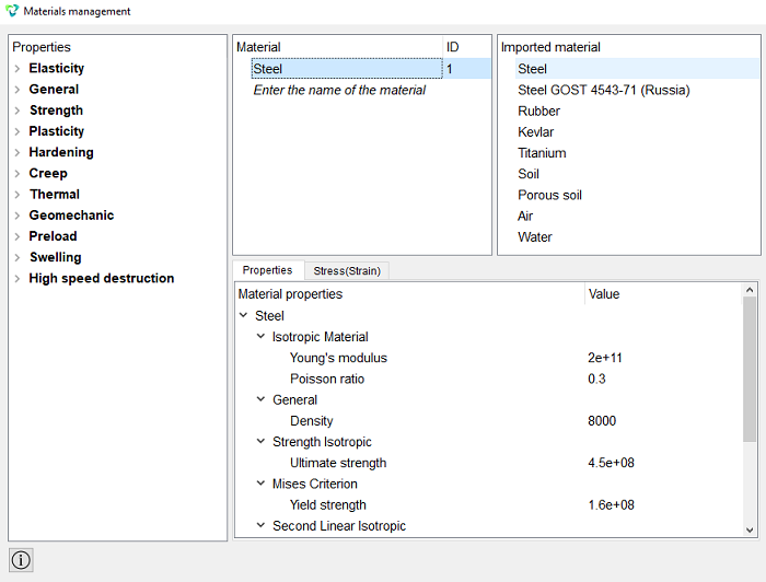
Click Apply.
Close the Materials management window.
2. Create a block.
On the command bar, select the block management module (Mode — Blocks, Entity — Block, Action — Add).

Set the following parameters:
Entity List: Volume;
Entity ID(s): all.
Click Apply.
3. Set the block parameters.
On the command bar, select the block management module (Mode - Blocks, Entity - Block, Action - Block properties/parameters).

Set the following parameters:
Block ID(s): 1;
Category: Solid;
Materials: Steel;
Coordinate System: Global Cartesian;
Order: 1.
Click Apply.
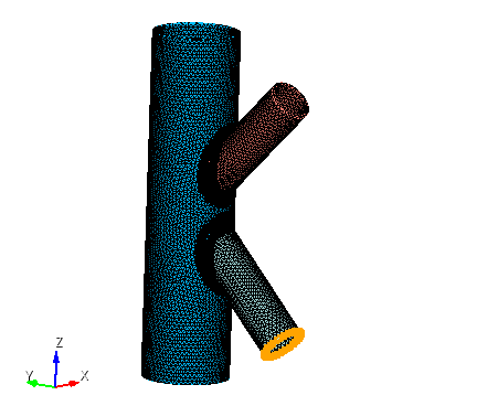
1. Lock the model in a cartesian coordinate system.
On the command panel, select the boundary conditions module (Mode — Boundary Conditions, Entity — Displacement, Action — Create).

Set the following parameters:
Entity List: Surface;
Entity ID(s): 57;
Degrees of Freedom: Fix All.
Click Apply.
2. Set the distributed force.
On the command panel, select the boundary conditions module (Mode — Boundary Conditions, Entity — Distributed Force, Action — Create).
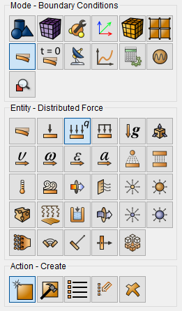
Set the following parameters:
Entity List: Surface;
Entity ID(s): 9;
Force Type: Distributed Force;
Force: 2000000;
Direction Vector: X - 0, Y - 0, Z - 1.
Click Apply.
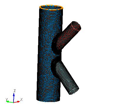
1. Specify the type of task you want to solve.
On the command bar, select the calculation settings module (Mode — Calculation Settings, Settings Calculation — Static, Static — General).

Set the following parameters:
Dimension: 3D;
Model: Elasticity.
Click Apply.
Click Start Calculation.
2. In a pop-up window select a folder to save the result and enter the file name.
3. In the case of a successful calculation, the console displays the message: Calculation finished successfully at "date" "time".
1. Open the file with the results. There are three ways to do that.
Click Ctrl+E.
From the main menu, select Calculation. Click Open Results.
Select Results on Command Panel (Mode - Results). Click Open results.

The FidesysViewer window will appear, in which you can view the calculation results.
2. Divide the model into two parts.
Apply the "Clip" filter. To do this, on the command bar, select Filters - Alphabetical - Clip.
In properties, click Apply.
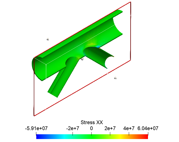
3. Display a plot of voltage linearizations.
On the command bar, select Filters - Alphabetical - Stress/Strain Linearization.
In the properties, enter the parameters:
Array Name To Process: Stress;
Array Components To Process: ХХ;
Resolution: 1000;
Point 1: -0.0188972 -0.122864 -0.0202038;
Point 2: 0.0328671 -0.0325662 -0.0561629.
Click Apply.
Geometry creating, meshing, setting boundary conditions and materials can be performed using the console interface. Below is a link to the program code that allows you to perform the steps described above manual, you only need to specify the full path and name.