Search the documentation
Enter at least 2 characters
Enter at least 2 characters
 |
CAE Fidesys 9.0 Documentation |
Source - GOST R 59115.9—2021. Equipment strength justification and pipelines of nuclear power plants. Verification calculation for strength
Linearization of the stress distribution should be carried out to isolate components of stress categories from a general stress state. Linearization can be performed both over the entire cross section of the component and along the wall thickness (i.e. along the line). For example, to highlight common bending stresses in the component should be linearized over the entire cross-section component, and to determine local membrane and local bending stresses Linearization should be performed along the wall thickness. The section along which carry out linearization, called the reduction cross section (CS). Line, by which linearization is carried out is called the reduction line (LR).
CS should be carried out through the area of the component where the first appearance of plastic deformations. If the component is a cylindrical shell, then the cross-section should be carried out perpendicular to the middle surface of the shell. Otherwise It is recommended to choose a joint perpendicular to one of the external surfaces.
The LR should be carried out through the wall of the structure, perpendicular to the internal one, outer or middle surface of a component. Examples of drug selection are given in Figure 1.
The stress state at each point CS and LR is characterized by the tensor stresses {σ}. The goal of the linearization procedure is to find a linear stress distribution along CS or LR, statically equivalent to the distribution obtained when calculating VAT in a component, i.e. having the same main force vector and main moment.
Based on the components of linearized stresses, the reduced stresses are determined categories σm, σmL(membrane) and σb, σbL (bending). To determine the reduced voltage categories σm⊕σb (total membrane and bending) components of linearized average and bending stresses are summed algebraically.
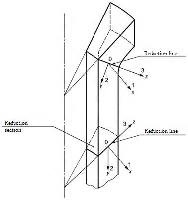
Figure 1. Example of CS and LR
If CS is flat, then the stress state at each point of the section can be represent as the sum of average, bending and nonlinear stress components σm αβ+σb αβ+σni αβ. At the same time, the values b and a, characterizing the average (membrane) and bending stress components, constant for all CS points
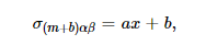
where b and a are coefficients that determine the average (membrane) and bending components respectively; x - distance from the central axis, relative which the general bending of CS occurs.
Average (membrane) stress components are constant for all points CS and equal
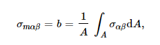
where A is the area CS.
The bending stress components vary linearly across the section and are equal
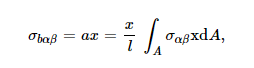
where  - moment of inertia CS relative to the central axis.
Nonlinear stress components should be calculated using the formula

The stress state at each point lying on LR is also represented (see Figure 2) as the sum of average, bending and nonlinear components stresses σm αβ+σb αβ+σnl αβ. Wherein coefficients that determine the membrane and bending stress components constant for all points LR
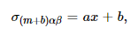
where x is the distance from the middle surface to the point in question, lying on LR.
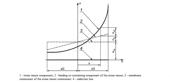
Figure 2. Separation of total stresses on the average, bending and nonlinear components for LR
Average (membrane) stress components are constant for all points LR and equal
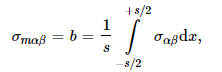
where s is the length of LR.
The bending stress components vary linearly along LR and are equal
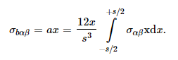
At the ends of LR the bending stresses take the values
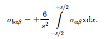
Nonlinear stress components should be calculated using the formula

The deformed state at each point lying on LR can be presented as the sum of average, bending and nonlinear strain components εm αβ+εb αβ+εnl αβ. At the same time, the values
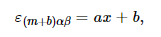
where x is the distance from the middle surface to the point in question, lying on LR.
Average (membrane) strain components are constant for all points LR and equal
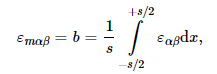
where s is the length of LR.
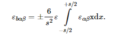
The bending components of the deformations vary linearly along LR and are equal
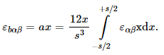
At the ends of LR, the bending strains take values
To call the Stress/Strain Linearization filter, you can use Menu - Filters - Alphabetical.
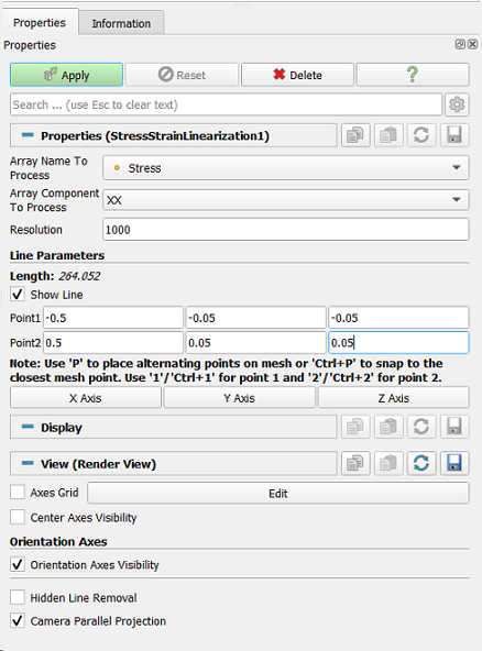
Figure 3. Filter properties Linearization Stress/Strain
Step by step example for applying the Stress/Strain Linearization filter.