Search the documentation
Enter at least 2 characters
Enter at least 2 characters
 |
CAE Fidesys 9.0 Documentation |
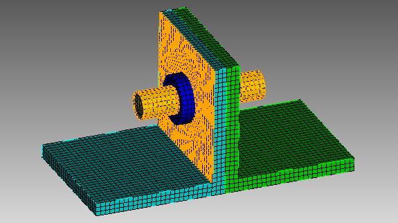
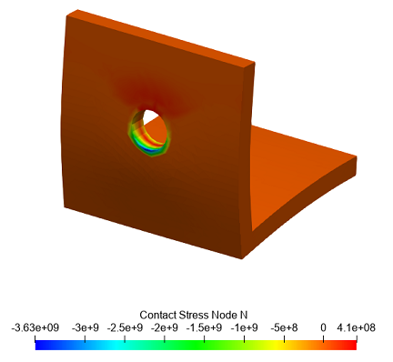
A small assembly with angles, a bolt and nuts is considered. Between every corner bolt and nut rigid contact, common contact between the corners. According to the calculation results it can be seen that a separation and pressing between the corners is formed. In the pressure zone, there are maximum normal stresses equal to zero in the separation zone.
1. Download the model from the link: Download ugolok.stp. If you cannot download the model, right-click on its name and select Save target as.... Then specify the folder where you want to go. place it.
The file can also be found in the folder C:\Program Files\Fidesys\CAE-Fidesys-9.0\preprocessor\bin\help\fidesys_example_tutorials\TestsFromHelp\models and select the specified model.
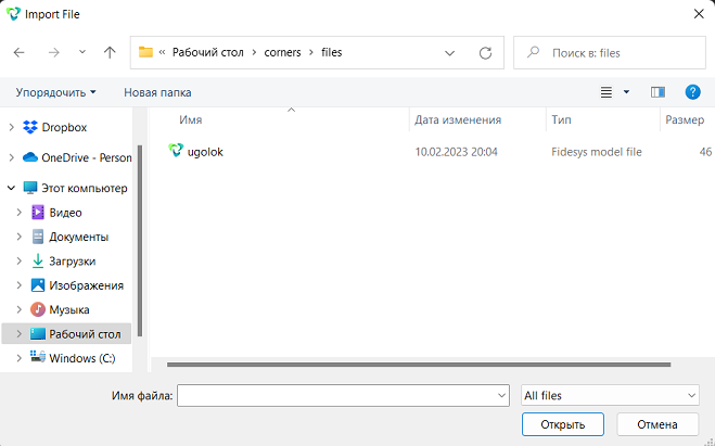
2. Import the model. On the top line, select (Menu - File - Import). Specify the path to the file ugolok.stp. In the window that appears, leave import settings unchanged.
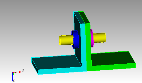
1. Create a mesh for all parts.
On the command bar, select the volume mesh module (Mode — Mesh, Entity - Volume, Action - Mesh).
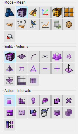
From the drop-down list, select Automatic Sizing.
Set the following parameters:
Select Volumes: 1 2 3 4 5;
Auto Factor: 4.
Click Apply Size.
Click Mesh.
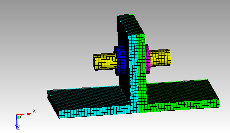
1. Specify the material.
In the command bar, select the module for specifying material properties (Mode — Material, Entity — Materials Management).

In the column "Imported material", double-click on Steel.
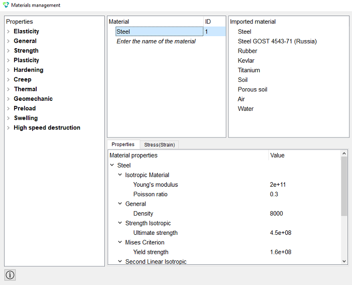
Click Apply.
Close the Materials management window.
2. Create a block.
On the command bar, select the block management module (Mode — Blocks, Entity — Block, Action — Add).

Set the following parameters:
Entity List: Volume;
Entity ID(s): all.
Click Apply.
3. Set the block parameters.
On the command bar, select the block management module (Mode - Blocks, Entity - Block, Action - Block properties/parameters).

Set the following parameters:
Block ID(s): 1;
Category: Solid;
Materials: Steel;
Coordinate System: Global Cartesian;
Order: 1.
Click Apply.
1. Lock the model in a cartesian coordinate system.
On the command panel, select the boundary conditions module (Mode — Boundary Conditions, Entity — Displacement, Action — Create).

Set the following parameters:
Entity List: Surface;
Entity ID(s): 6;
Degrees of Freedom: Fix All.
Click Apply.
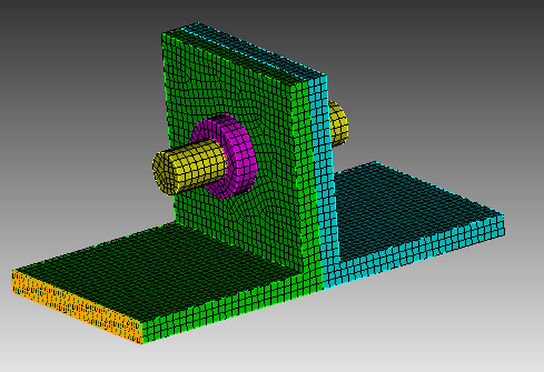
2. Set the distributed force.
On the command panel, select the boundary conditions module (Mode — Boundary Conditions, Entity — Distributed Force, Action — Create).
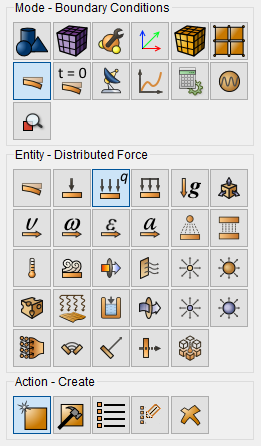
Set the following parameters:
Entity List: Surface;
Entity ID(s): 26;
Force Type: Distributed Force;
Check the box: Specify Using Vector;
Force X: {-1e4/9e-05};
Force Y: 0;
Force Z: 0;
Moment X: 0;
Moment Y: 0;
Moment Z: 0.
Click Apply.
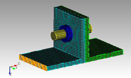
3. Scale the volumes.
On the command panel select (Mode - Geometry, Entity - Volume, Action — Transform).
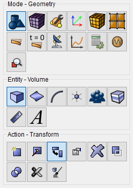
Select Scale from the dropdown list.
Set the following parameters:
Select: Uniform Scaling;
Scale Factor: 1e3.
Click Apply.
4. Set the contact between the corner surfaces.
On the command panel, select the boundary conditions module (Mode — Boundary Conditions, Entity — Contact, Action — Create).
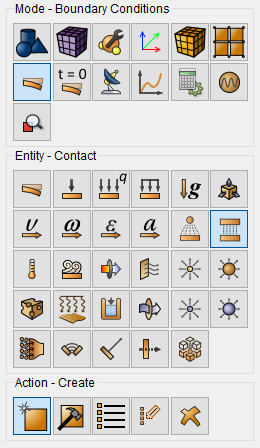
From the drop-down list, select: Auto Selection.
Set the following parameters:
Entity List: Volume;
Entity ID(s): 1 4;
Type: General;
Friction Value: 0.0;
Offset: 0.0;
Tolerance: 0.0005;
Method: Auto.
Click Apply.
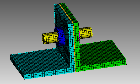
5. Define the bonded contact between the surfaces of the assembly.
On the command panel, select the boundary conditions module (Mode — Boundary Conditions, Entity — Contact, Action — Create).
From the drop-down list, select: Auto Selection.
Set the following parameters:
Entity List: Volume;
Entity ID(s): 1 3 2;
Type: Tied;
Offset: 0.0;
Tolerance: 0.0005;
Method: Auto.
Click Apply.
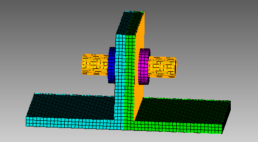
6. Define the bonded contact between the surfaces of the assembly.
On the command panel, select the boundary conditions module (Mode — Boundary Conditions, Entity — Contact, Action — Create).
From the drop-down list, select: Auto Selection.
Set the following parameters:
Entity List: Volume;
Entity ID(s): 4 5 2;
Type: Tied;
Offset: 0.0;
Tolerance: 0.0005;
Method: Auto.
Click Apply.
7. Scale the volumes.
On the command panel select (Mode - Geometry, Entity - Volume, Action — Transform).
Select Scale from the dropdown list.
Set the following parameters:
Select: Uniform Scaling;
Scale Factor: 1e-3.
Click Apply.
1. Set the type of problem you want to solve.
On the command bar, select the calculation settings module (Mode — Calculation Settings, Settings Calculation — Static, Static — General).

Set the following calculation parameters:
Dimensions: 3D;
Model: Elasticity;
Model: Plasticity;
Set Nonlinear Solver Options;
Start Load Substeps: 10;
Min Load Substeps: 10;
Max Load Substeps: 1000;
Max Iterations: 100;
Tolerance: 0.001;
Target Iterations: 5.
Click Apply.
Click Start Calculation.
2. In a pop-up window select a folder to save the result and enter the file name.
3. In the case of a successful calculation, the console displays the message: Calculation finished successfully at "date" "time".
1. Open the file with the results. There are three ways to do that.
Click Ctrl+E.
From the main menu, select Calculation. Click Open Results.
Select Results on Command Panel (Mode - Results). Click Open results.

The FidesysViewer window will appear, in which you can view the calculation results.
2. Apply a filter "Warp By Vector" in order to display the results in a deformed way. On the top line, select (Filters - Alphabetical - Warp By Vector).
In Properties select:
Vectors: Displacement;
Move the scale factor;
Representation: Surface.
Click Apply.
From the first dropdown select Stress, from the second select Mises.
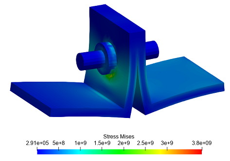
3. Check the voltage at the contact node. Apply a filter "Threshold" in order to leave the desired part of the geometry. On the top line, select (Filters — Alphabetical - Threshold).
In Properties select:
Input Array: Parent ID;
Minimum: 1;
Maximum: 1.
Click Apply.
From the first drop-down list, select Contact Stress Node, from the second - N.
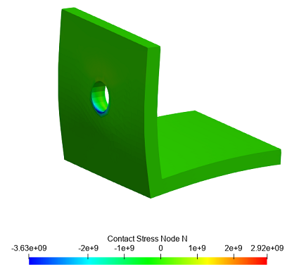
4. Check the stress at the contact node near the separation zone. Zoom
in desired area, then on the top panel apply Rescale to Visible Data
Range. 
Geometry creating, meshing, setting boundary conditions and materials can be performed using the console interface. Below is a link to the program code that allows you to perform the steps described above manual, you only need to specify the full path and name.