Search the documentation
Enter at least 2 characters
Enter at least 2 characters
 |
CAE Fidesys 9.0 Documentation |
Static calculation of rod elongation under the influence of changes in the temperature environment.
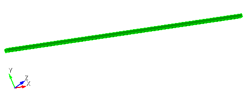
1. Create a brick.
On the command bar, select the module for constructing volume geometry (Mode — Geometry, Entity — Volume, Action — Create).

From the list of geometric primitives, select Brick.
Set the following parameters:
X (width): 1;
Y (height): 0.01;
Z (depth): 0.01.
Click Apply.
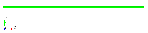
1. Create a mesh for the entire model.
On the command bar, select the volume mesh module (Mode — Mesh, Entity – Volume, Action – Intervals).
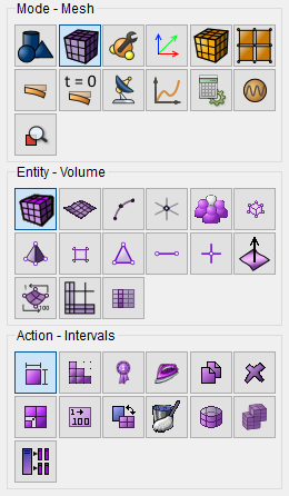
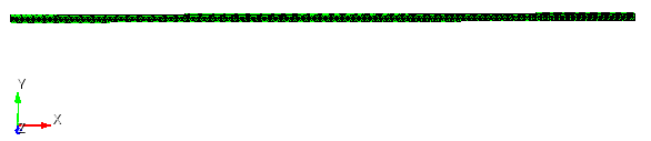
From the pop-up list, select: Automatic Sizing.
Select Volumes: 1;
Auto Factor: 5.
Click Apply Size.
Click Mesh.
1. Specify the material.
In the command bar, select the module for specifying material properties (Mode — Material, Entity — Materials Management).

In the column "Imported material", double-click on Steel.
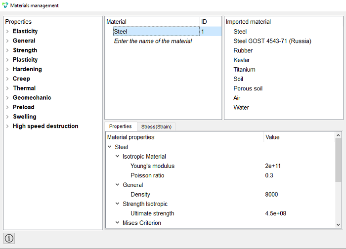
Click Apply.
Close the Materials management window.
2. Create a block.
On the command bar, select the block management module (Mode — Blocks, Entity — Block, Action — Add).

Set the following parameters:
Entity List: Volume;
Entity ID(s): 1.
Click Apply.
3. Set parameters for blocks.
On the command bar, select the block management module (Mode — Blocks, Entity — Block, Action — Block properties/parameters).

Set the following parameters:
Block ID(s): 1;
Category: Solid;
Material: Steel;
Coordinate System: Global Cartesian;
Order: 2.
Click Apply.
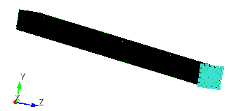
1. Fix the end part of the parallelepiped along the X-axis.
On the command panel, select the boundary conditions module (Mode — Boundary Conditions, Entity — Displacement, Action — Create).

Set the following parameters:
Entity List: Surface;
Entity ID(s): 4;
Degrees of Freedom: X.
Click Apply.
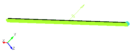
2. Fix the model on the Y axis.
On the command panel, select the boundary conditions module (Mode — Boundary Conditions, Entity — Displacement, Action — Create).
Set the following parameters:
Entity List: Surface;
Entity ID(s): 3;
Degrees of Freedom: Y.
Click Apply.
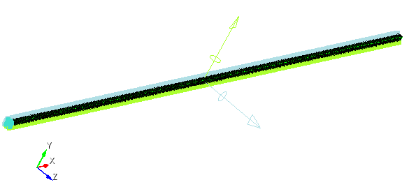
3. Fix the model on the Z axis.
On the command panel, select the boundary conditions module (Mode — Boundary Conditions, Entity — Displacement, Action — Create).
Set the following parameters:
Entity List: Surface;
Entity ID(s): 2;
Degrees of Freedom: Z.
Click Apply.
4. Set the temperature on the entire model.
On the command panel, select the boundary conditions module (Mode — Boundary Conditions, Entity — Temperature, Action — Create).
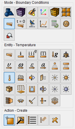
Set the following parameters:
Entity List: Volume;
Entity ID(s): 1;
Value: 400.
Click Apply.
1.Specify the type of task you want to solve.
On the command bar, select the calculation settings module (Mode — Calculation Settings, Settings calculation — Static, Static — General).

Select:
Dimension: 3D;
Model: Elasticity;
Model: Heat Transfer.
Click Apply.
2. Set the ambient temperature.
On the command bar, select the calculation settings module (Mode — Calculation Settings, Calculation Settings — Static, Static — Environment Properties).
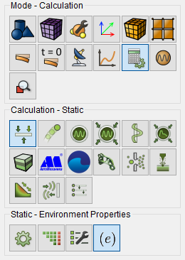
Temperature: 300.
Click Apply.
Click Start Calculation.
3. In the window that appears, select the directory where the result will be saved and enter the file name.
4. In the case of a successful calculation, the console displays the message: Calculation finished successfully at "date" "time".
1. Open the file with the results. There are three ways to do that.
Click Ctrl+E.
From the main menu, select Calculation. Click Open Results.
Select Results on Command Panel (Mode - Results). Click Open results.

A window will appear FidesysViewer, in which you can read with the results of the calculation.
2. Check the change in the length of the rod. On the top panel, select: Displacement → X.
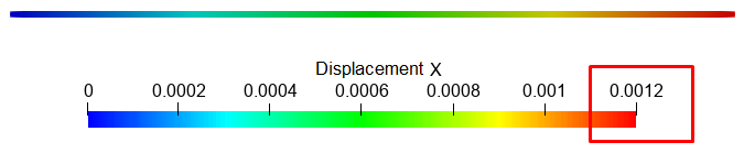
This result can be obtained by the formula:

Where:
l is the length of the body at the initial temperature.
l' is the length of the body when the temperature changes.
α is the stress intensity coefficient.
t - body temperature.
t' is the temperature of the medium.
Geometry creating, meshing, setting boundary conditions and materials can be performed using the console interface. Below is a link to the program code that allows you to perform the steps described above manual, you only need to specify the full path and name.