Added display of 3D beam sections in the preprocessor
To display a 3D section view for beam elements in the preprocessor,
click on the corresponding button on the top panel.

|
Improved algorithm for generating triangular mesh
Now options Applying material, Coordinate system, Type and Order
of finite elements for a block is combined in one panel Block
Properties / Parameters

Block
Properties / Parameters |
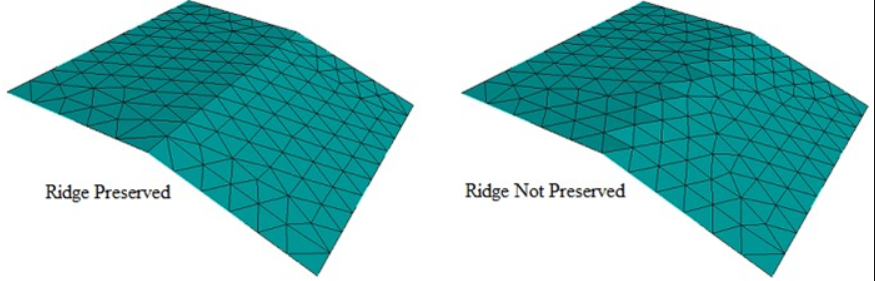
New Setting in Triangle Meshing Scheme to Preserve Ridge Angle
when Meshing Discrete Geometry
When meshing discrete geometry (mbg/facet-based or composite
surface) the ridge_angle setting can allow triangle meshing to
capture or wash over lines or 'ridges' in the discrete geometry.
[Set] Trimesher Ridge Angle {}
|
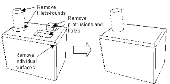
New Options for Remove Surface Command
The remove surface command includes the keywords blend_chain
and cavity.
|
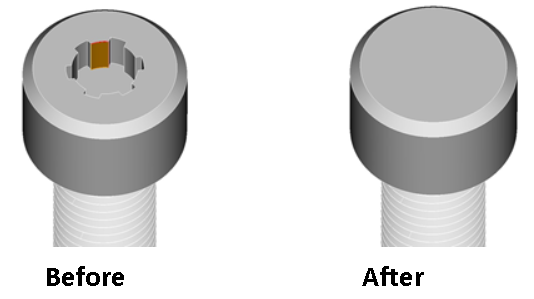
New Remove Cavity and Blend_chain Command
The remove surface and tweak surface remove commands now provide
new options to automatically include attached surfaces that are
defined within a blend_chain or cavity.
Remove Surface [blend_chain] [cavity] [EXTEND|noextend] [keepsurface]
[keep] [individual] [preview]
|
Enhanced Collapse Angle at Vertex Command
The collapse angle at vertex command is often used to modify
the angle at tangent vertices to improve mesh quality. Previously
this option required manual specification of adjacent curves and
other parameters. It now allows for default parameter selection
making it easier to use. It now also provides a real_split option
in place of virtual partitioning as well as input of a range of
vertex IDs.
Collapse Angle At Vertex [angle ] [real_split] [Curve [Arc_length
]] [Curve [Arc_length | Perpendicular | Same_size | Tangent]]
[composite_vertex ] [preview]
The collapse angle at vertex command is an alternative to the
blunt tangency operation that can sometimes fail under certain
circumstances. This expands the available tool suite that can
be used for defeaturing and improving meshing outcomes. Note that
in most cases, syntax for this command can simplified to the following:
Collapse Angle At Vertex [angle ] [real_split]
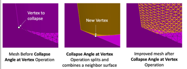
The following figure illustrates a common use case for the collapse
angle at vertex operation.
|
Remove Overlap Volume Command
The remove overlap volume command can be used to perform a boolean
operation to remove the overlapping region between two volumes
Remove Overlap Volume {Modify | Smaller | Larger}
The Modify argument in this command is used to identify which
of the two volumes where material will be subtracted. The new
optional Smaller or Larger arguments can be used to indicate which
volume to modify based on its relative geometric volume without
the need to indicate an ID. |
Refactor of Geometry Power Tools
The Geometry Power Tools have been refactored to be more robust,
to provide more efficient operations, and to incorporate some
of the ITEM-like behaviors.
The geometry power tool is an interactive environment for rapidly
analyzing and defeaturing geometry. This tool has been significantly
enhanced in version 17.1. Some of the new features include the
following:
- Automatic default for Small Curve Threshold
- Auto Update provides the option to automatically recompute
diagnostic tests after each geometry operation.
- A new solution view that provides specific geometry operations
based on currently selected entity.
- Enhanced context (right click) options for entity selection
based on similar geometry characteristics.
- New diagnostic tests for identifying cavities and holes
- Enhanced options to control diagnostic threshold for blend
surface radius and cavity/hole area.
|
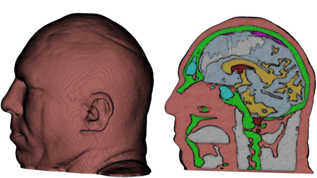
Improved Sculpt Automatic All-hex Meshing technology
Sculpt is a companion application for parallel automatic hex
meshing. It can be run from the Fidesys GUI or directly from the
OS using an input file. The following new Sculpt options are currently
available from an input file only.
Separate Void Blocks
When the mesh_void option is used, the default case will generate
a single block ID for all elements in the void region. Turning
this option ON will separate the elements into unique block IDs
where the elements are contiguous.
Input Mesh Material based on Proximity
When using the input_mesh option as the overlay grid definition,
the resulting material/block definitions are normally prescribed
based on either the STL geometry or by the element blocks in the
input file using the input_mesh_material option. The new proximity_blocks
(2) argument will cut the overlay grid using the STL geometry
definition, however the final element block assignment will be
based on the location or proximity of the final elements to the
blocks prescribed in the input_mesh. This is useful when the block
definition in the input_mesh does not precisely align with the
STL geometry.
Compute Sideset Statistics
The new compute_ss_stats option will report the surface area
statistics of resulting sidesets in the exodus mesh. This is often
useful for microstructures where it may be important to know the
interface area between materials. This should be used with the
gen_sidesets option to be effective.
|